Radio may be dead in terms of delivering entertainment, but it’s times like these when the original social network comes into its own. Being able to tune in stations from across the planet to get fresh perspectives on a global event can even be a life saver. You’ll need a good antenna to do that, which is where this homebrew loop antenna for the shortwave radio bands shines.
 To be honest, pretty much any chunk of wire will do as an antenna for most shortwave receivers. But not everyone lives somewhere where it’s possible to string up a hundred meters of wire and get a good ground connection, which could make a passive loop antenna like this a good choice. Plus, loops tend to cancel the electrical noise that’s so part of life today, which can make it easier to pull in weak, distant stations.
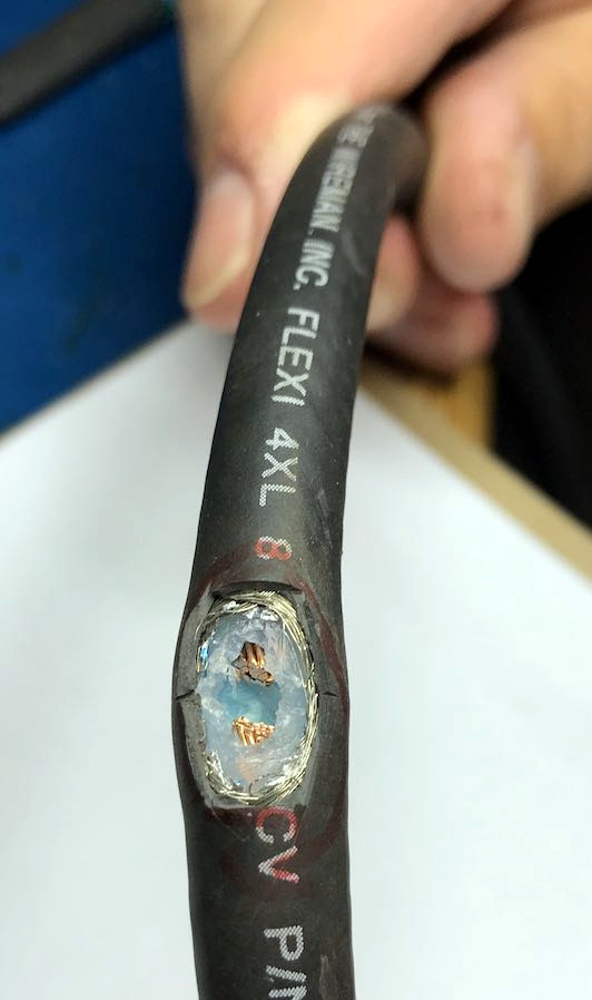
[Thomas]’s design is based on a length of coaxial cable, which should be stiff enough to give the loop some stability, like a low-loss RG-8 or RG-213. The coax braid and dielectric are exposed at the midpoint of the cable to create a feed point, while the shield and center conductor at the other ends are cross-connected. A 1:1 transformer is wound on a toroid core to connect to the feedpoint; [Thomas] calls it a balun but we tend to think it’s more of an unun, since both the antenna and feedline are unbalanced. He reports good results from the loop across the shortwave band.
The shortwave and ham bands are a treasure trove of information and entertainment just waiting to be explored. Check them out — you might learn something, and you might even stumble across spies doing their thing.
[via RTL-SDR.com]