Digital TV Converter Reverse Engineering

Back when broadcast television was first switching over from analog to digital most people needed to get a converter box to watch DTV broadcasts. Remember that abomination that was “HD-Ready”? Those TVs could display an HD signal, but didn’t actually have a digital tuner in them. Nowadays all TVs come with one, so [Craig] found his old converter box was just gathering dust. So he cracked it open and reverse engineered how the DTV hardware works.

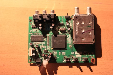
The hardware includes a Thompson TV tuner, IR receiver for the remote control, and the supporting components for an LGDT1111 SoC. This is an LG chip and after a little searching [Craig] got his hands on a block diagram that gave him a starting place for his exploration. The maker of the converter box was also nice enough to include a pin header for the UART. It’s populated and even has the pins labeled on the silk screen. We wish all hardware producers could be so kind. He proceeds to pull all the information he can through the terminal. This includes a dump of the bootloader, readout of the IR codes, and much more.

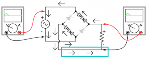
Experimenting With Bridge Rectifers For AC To DC Power Conversion

The folks over at Toymaker Television have put together another episode. This time they’re looking at bridge rectifiers and how they’re used in AC to DC converters.

This is a simple concept which is worth taking the time to study for those unfamiliar with it. Since Alternating Current is made up of cycles of positive and negative signals it must be converted before use in Direct Current circuits; a process called rectification. This is done using a series of 1-way gates (diodes) in a layout called a bridge rectifier. That’s the diamond shape seen in the diagram above.

This episode, which is embedded after the break, takes a good long look at the concept. One of the things we like best about the presentation is that the hosts of the show talk about actual electron flow. This is always a quagmire with those new to electronics, as schematics portray flow from positive to negative, but electron theory suggests that actual electron flow is the exact opposite. Continue reading “Experimenting With Bridge Rectifers For AC To DC Power Conversion”

Broken Laptop Recovered Using An Arduino

We see Arduino boards used in a lot of projects but we’ve never thought of using one as a USB crossover cable. That’s basically what [Jack the Vendicator] did to get his broken laptop running. When his video card stopped working he found himself unable to access the laptop. Newer machines don’t have a serial connector, which could have been used for a serial terminal, so he was at a bit of a loss since neither SSH nor VNC were installed. But he thought he might be able to use the Arduino as a serial terminal connector over USB. He plugged the Arduino into the laptop, and connected a USB serial converter from his desktop computer to the Arduino’s serial pins. In effect he’s just taking advantage of the FTDI chip, translating those signals back into USB on either end. Once he booted the headless laptop it took just a couple of blindly typed commands to get SSH running in order to regain control.

Power Supplies And Transformers; A Learning Experience

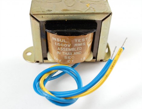
[Ladyada] is working on a tutorial series covering power supplies. If you’ve ever built an electronic project you’ve used some type of power supply but we think that most people have no idea how you get from mains power to the DC voltages that most small projects use. So if you want to learn, get started with the first installment which covers AC/DC converters based on a transformer like the one seen above.

These transformers are inside the heavy and hot wall-wart plugs that come with many electronics. We used one along with a breadboard power supply when building the pumpkin LED matrix. They use a pair of coils to step down the voltage to a much smaller level. From there it’s a matter of rectifying the AC into DC power, which she talks about in an easy to follow discussion.

We understand this type of converter quite well but we’re a bit foggy on switch-mode AC/DC converters that don’t use a transformer. They’re much better because you don’t have to build a regulator into the target project like you do with wall-warts. Can’t wait until she gets to that part of the series!

Building A Power Supply Around A DC-DC Converter

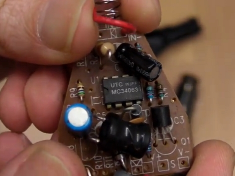
The EEVblog is on a roll with interesting topics lately. In the latest episode [Dave] takes us through the nitty-gritty of switch mode power supply design. Using DC-DC converter IC’s in not especially hard. The datasheets tend to have fairly good usage schematics but there’s always a bit of heartache that goes into figuring out which external components will make for an optimal design. Get your calculator out and, in the video after the break, he’ll walk you through choosing component values based on the formulas for the MC34063 converter chip.

[Dave] makes the point that this is an extremely common chip, available from several manufacturers, and often found in consumer electronics. In fact, the switchmode supply hack from last month was using a regulator based around the MC34063. So you can buy it or scavenge for it. One thing to note though, we checked Mouser and Digikey and they’re pretty short on these chips right now. Plan your projects accordingly.

Continue reading “Building A Power Supply Around A DC-DC Converter”

Building A Glue Stick Flashlight

Building an LED flashlight is simple, right? Take a battery, connect it to an LED by way of a resistor. Alright wise guy, now make one that steps up the voltage for multiple LEDs and don’t use a boost-converter IC to do so.

[fede.tft] shares a flashlight built inside of a  used glue stick case. It’s the perfect size for one AA battery (we’re always on the lookout for good battery cases), and a shape that we’re familiar with as a flashlight. The problem is that he wants two white LEDs but with just one AA cell he’s never going to have more that 1.5V available. He licked that problem, getting to 7.2V by designing his own step-up converter using one transistor, an inductor, and three passive components. To get the inductor he needs, a stock part is disassembled and rewound to suit. Maybe you just end up with a flashlight when all is said and done, but then again, the Sistine Chapel is just some paintings on a ceiling.

SparkFun’s Logic Level Converter


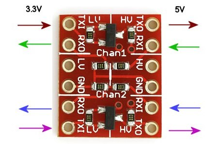
SparkFun has always been good about designing and stocking useful breakout boards. This recently added Logic Level Converter is no exception. It’s uses two BSS138 MOSFETs to shift 5V logic levels to 3.3V. The board handles two separate serial pairs. Just hook up the RX and TX on either side. Provide power at both voltages and the board will happily do the conversion. It’s $2, smaller than the size of a quarter, and perfect for plugging into a breadboard.