CircuitMaker From Altium

Altium recently announced CircuitMaker, their entry into the free/low-cost PCB design tool market. They’re entering a big industry, with the likes of Eagle, KiCad, gEDA, and a host of other tool suites. We had a few minutes to talk with Max in the Altium booth at World Maker Faire, and even got a bit of time with the tool itself.

Hands on, it definitely has the look and feel of Altium Designer, right down to the familiar yellow and green boxes for schematic and sheet parts. Center stage was the 3D view, a feature which Altium has had in their software since the late 90’s.

CircuitMaker’s website is pushing the collaboration aspect of the software. Design choices can be reviewed and commented on in real-time. This also suggests that the data files will live in Altium’s own cloud storage system.

CircuitMaker is still in the pre-beta phase, but they’re looking for beta testers now, so head over to the site and sign up!

Extending EagleCAD With Python

eagleAlthough it’s derided for not being open source, EagleCAD is an extremely popular piece of schematic and PCB layout software. Most of the popularity is probably due to the incredible amount of part libraries – it’s certainly not the features Eagle has to offer or its horrible scripting capabilities. [Rob] had enough of the lack of good scripting support in Eagle, so he’s been spending his time making Eagle’s ULP work with Python. He’s only been at it a short time, but already it’s much more usable than the usual Eagle scripts.

Below you can check out a pair of videos of [Rob]’s Python tools for Eagle in action. The first video goes through aligning a few symbols and creating a board outline (with proper curves!) from a DXF file. The second video shows exactly how valuable these tools are when laying out a board: imagine hundreds of LEDs and resistors automatically aligned to each other with a single click of a mouse. Beautiful.

All the PyEagle stuff is available on [Rob]’s github, with a DXF importer, group manager, and alignment tool included. Now that everything’s Python, it’s easy to build your own tools without relying on Eagle’s odd ULP language.

Continue reading “Extending EagleCAD With Python”

One-Off Kapton Solder Masks

soldermask

With the proliferation of desktop routers, and a number of easy methods to create PCBs at home, there’s no reason anyone should ever have to buy a pre-made breakout board ever again. The traditional techniques only give you a copper layer, however, and if you want a somewhat more durable PCB, you’ll have figure out some way to create a solder mask on your homebrew PCBs. [Chris] figured Kapton tape would make a reasonable soldermask, and documented the process of creating one with a laser cutter over on the Projects site.

The solder mask itself is cut from a piece of Kapton tape, something that should be found in any reasonably well-stocked tinkerer’s toolbox. The software for [Chris]’ laser cutter, a Universal Laser Systems model, already has a setting for mylar film that came in handy for the Kapton tape,

Of course, getting the correct shapes and dimensions for the laser to cut required a bit of fooling around in Eagle and Corel Draw. The area the laser should cut was taken from the tCream and tStop layers in Eagle with a 1 mil pullback from the edges of the pads. This was exported to an .EPS file, opened in Corel Draw, and turned into a line art drawing for the laser cutter.

The result is a fast and easy solder mask that should be very durable. While it’s probably not as durable as the UV curing paints used in real PCBs, Kapton will be more than sufficient for a few prototypes before spinning a real board.

A Touch Scroll Wheel Via OpenSCAD

touch

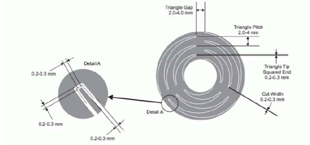
Recent experiments with the Arduino CapSense library led [Bryan] around the Internet looking for interesting applications. He hit upon a very cool touch scroll wheel made entirely with PCB traces, but the geometry – three interleaved zig zags is impossible to build in the decidedly ungeometric Eagle PCB package. One thing leads to another and now [Bryan] has a cap touch wheel Eagle part designed entirely in OpenSCAD.

The touch scroll wheel implementation [Bryan] found came from an ST touch controller datasheet and used oddly-shaped patterns to create a capacities sensor. Eagle is terrible for designing anything that isn’t laid out at a 45 degree angle, so he fired up OpenSCAD to draw these triangles. Importing into Eagle was another challenge, but a quick Ruby script to convert a DXF file into a set of coordinates for Eagle’s POLYGON command made everything very easy.

If OpenSCADing touch sensors isn’t your thing, there’s also an Eagle library full of them – something we found last week.

Easy Capacitive Touch Sensors In Eagle

board

Capacitive sensing libraries for the Arduino and just about every other microcontroller platform have been around for ages now, but if you’d like to put a slightly complex cap sense pad in a PCB without a lot of work, you’re kind of out of luck. Not only do you need a proper education in how capacitors work, but a custom cap sense pad also requires some advanced knowledge of your preferred PCB layout program.

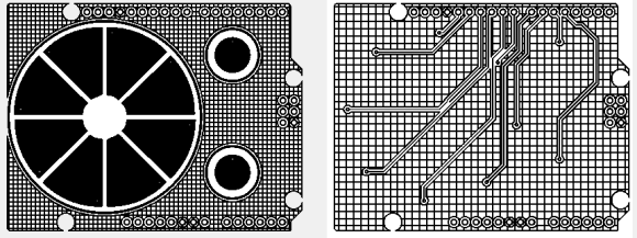
The folks over at PatternAgents have just the solution for this problem. They created an Eagle library of touch widgets that includes everything from buttons, linear and radial sliders, touchpads, and a whole lot more.

The simplest cap sense pad is just a filled polygon on the top layer of a board, but this simple setup isn’t ideal if you want to use Eagle’s autorouter. By playing with the restrict layers in Eagle, PatternAgents were able to create easy cap sense buttons that will work perfectly, without the problems of the autorouter placing traces willy-nilly.

There are more than enough parts to replicate a whole lot of touch interfaces – buttons can easily be made into a smallish keyboard, and the radial touch sensor will emulate the ‘wheel’ interface on an iPod. Very cool stuff, and we can’t wait to see these in a few more boards.

KiCad Video Series: From Concept To Manufacture

Many of our readers took the habit of using Eagle to design their PCBs. Even if you’ll find plenty of support for this software as well as a lot of parts libraries, the software comes with limitations. The useable board area is limited to 4×3.2 inches, only two signal layers can be used and more importantly the schematics editor can only create one sheet. On the other side, some of you may already know KiCad, a free open source and unrestricted schematics and layout software. [Chris] just tipped us of a video series he made, showing people how to design and build their very first PCB using this software. It’s a simple 555 circuit, but goes through all the steps necessary to design a PCB that costs only $5 through OSHpark… and will blink by the end. All the videos are also embedded after the break.

Continue reading “KiCad Video Series: From Concept To Manufacture”

Make Any Shape Board In Eagle

circuit2

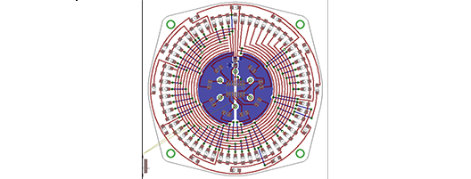
[Bryan] has been working on a very nice analog LED clock circuit, but when it came time to lay out the parts in Eagle, he was somewhat miffed by the inability to create designs in his Eagle boards. Eagle is a fine tool for laying out circuits, but when it comes to making strangely shaped PCBs, Eagle just isn’t the right tool.

The solution to this problem was to create the board outline in OpenSCAD. The desired shape of [Bryan]’s clock was easily designed, but importing the shape into an Eagle layer was another matter entirely.

OpenSCAD, though, can output 2D shapes to the DXF format. Getting the DXF board into Eagle required [Bryan] to write a script that outputs Eagle WIRE commands. Pasting these commands into the command line gave [Bryan] a perfectly shaped PCB.

Since DXF is supported by every drawing package on the planet, [Bryan]’s 20 line script could also be used for much more intricate designs. If you have an incredibly complex Illustrator drawing that deserves to be a PCB, it doesn’t get much easier than tossing it through a script.