LayerLapse Simplifies 3D Printer Time-lapse Shots

We know you’ve seen them: the time-lapses that show a 3D print coming together layer-by-layer without the extruder taking up half the frame. It takes a little extra work compared to just pointing a camera at the build plate, but it’s worth it to see your prints materialize like magic.

Usually these are done with a plugin for OctoPrint, but with all due respect to that phenomenal project, it’s a lot to get set up if you just want to take some pretty pictures. Which is why [Whopper Printing] put together the LayerLapse. This small PCB is designed to trigger your DSLR or mirrorless camera once its remotely-mounted hall effect sensor detects the presence of a magnet.

The remote hall effect sensor.

The idea is that you just need to stick a small magnet to your extruder, add a bit of extra G-code that will park it over the sensor at the end of each layer, and you’re good to go. There’s even a spare GPIO pin broken out should you want to trigger something else on each layer of your print. Admittedly we can’t think of anything else right now that would make sense, other than some other type of camera, but we’re sure some creative folks out there could put this feature to use.

Currently, [Whopper Printing] is selling the LayerLapse as a finished product, though it does sound like a kit version is in the works. There’s also instructions for building a DIY version of the hardware using your microcontroller of choice. Whether you buy or build the hardware, the firmware is available under the MIT license for your tinkering pleasure.

Being hardware hackers, we appreciate the stand-alone nature of this solution. But if you’re already controlling your printer through OctoPrint, you’re probably better off just setting up one of the available time-lapse plugins.

Brick Layer Post-Processor, Promising Stronger 3D Prints, Now Available

Back in November we first brought you word of a slicing technique by which the final strength of 3D printed parts could be considerably improved by adjusting the first layer height of each wall so that subsequent layers would interlock like bricks. It was relatively easy to implement, didn’t require anything special on the printer to accomplish, and testing showed it was effective enough to pursue further. Unfortunately, there was some patent concerns, and it seemed like nobody wanted to be the first to step up and actually implement the feature.

Well, as of today, [Roman Tenger] has decided to answer the call. As explained in the announcement video below, the company that currently holds the US patent for this tech hasn’t filed a European counterpart, so he feels he’s in a fairly safe spot compared to other creators in the community. We salute his bravery, and wish him nothing but the best of luck should any lawyer come knocking.

So how does it work? Right now the script supports PrusaSlicer and OrcaSlicer, and the installation is the same in both cases — just download the Python file, and go into your slicer’s settings under “Post-Processing Scripts” and enter in its path. As of right now you’ll have to provide the target layer height as an option to the script, but we’re willing to bet that’s going to be one of the first things that gets improved as the community starts sending in pull requests for the GPL v3 licensed script.

There was a lot of interest in this technique when we covered it last, and we’re very excited to see an open source implementation break cover. Now that it’s out in the wild, we’d love to hear about it in the comments if you try it out.

Continue reading “Brick Layer Post-Processor, Promising Stronger 3D Prints, Now Available”

Art of 3D printer in the middle of printing a Hackaday Jolly Wrencher logo

3D Printering: Switch And Klip(per)

Last time I tried to convince you that, if you haven’t already, you should try running your 3D printer with Klipper. There are several ways to actually make it work.

The first thing you need is something to run the Klipper host. Most people use a Raspberry Pi and if you already have one that runs OctoPrint, for example, you might well use it. Just tuck your SD card away in case you give up and install a fresh Linux system on a new card.

The Creality Sonic Pad has issues, but it does work.

However, a Pi isn’t your only option. You should be able to make it work on nearly anything that runs Linux. We’ve even seen it running on Windows under WSL. If you have an old laptop that can run Linux, that would work, too. We’ve even heard it works on a Chromebook.

The other option is to get a “pad.” Several vendors make touchscreens with some Linux single-board computer bundled together with Klipper preinstalled. For example, there is the Creality Sonic Pad, along with similar devices from other 3D printing companies.

If you decide to go that route, you might want to make sure it is easy to install your own software easily. Some pads, like the Creality unit, are notorious for having so much customization that they don’t lend themselves to upgrades unless they come from the manufacturer. In some cases, you can wipe out the stock firmware and install a normal operating system, but at that point, you could probably just buy a Pi and a touchscreen, right?

Continue reading “3D Printering: Switch And Klip(per)”

Art of 3D printer in the middle of printing a Hackaday Jolly Wrencher logo

3D Printering: Klipper, The Free 3D Printer Upgrade

I have several 3D printers, and I’ve always been satisfied with using either Repetier or Marlin on all of them. There are a few other firmware versions that could run on my hardware, but those two have been all I’ve needed. Sure, it was painful for a while having to juggle features to fit the firmware image onto the smaller microcontroller boards. Now that Marlin supports big 32-bit boards however, that hasn’t been a problem. But recently, I’ve been on a program to switch everything to Klipper.

In this post, I’ll tell you why I did it and give you some data about why you might consider it, too.

The Landscape

Marlin is written in C and burned into a 3D printer’s flash memory. It does a lot. It receives G-code commands, interprets them, and translates them to meaningful actions on the hardware. Modern versions handle automatic transformations to account for lumpy beds, input shaping to reduce shaking, and linear advance to produce better prints.

It might seem simple to control a 3D printer, but there are lots of little details to take into account. For example, if you are moving the head between two XY coordinates and you expect a certain flow rate, then you have to figure out how fast to turn the steppers to get the right amount of plastic out over that time. You also may have to retract before you start a move, make sure temperatures are stable, and transform the actual coordinates based on bed leveling data. There’s a lot going on.

Klipper does the exact same job, but it does it differently. On the 3D printer board is a tiny piece of software that does very little. It’s a bit like a device driver for the printer. All by itself, it does nothing. But it can handle very basic commands that describe how to move the machine.

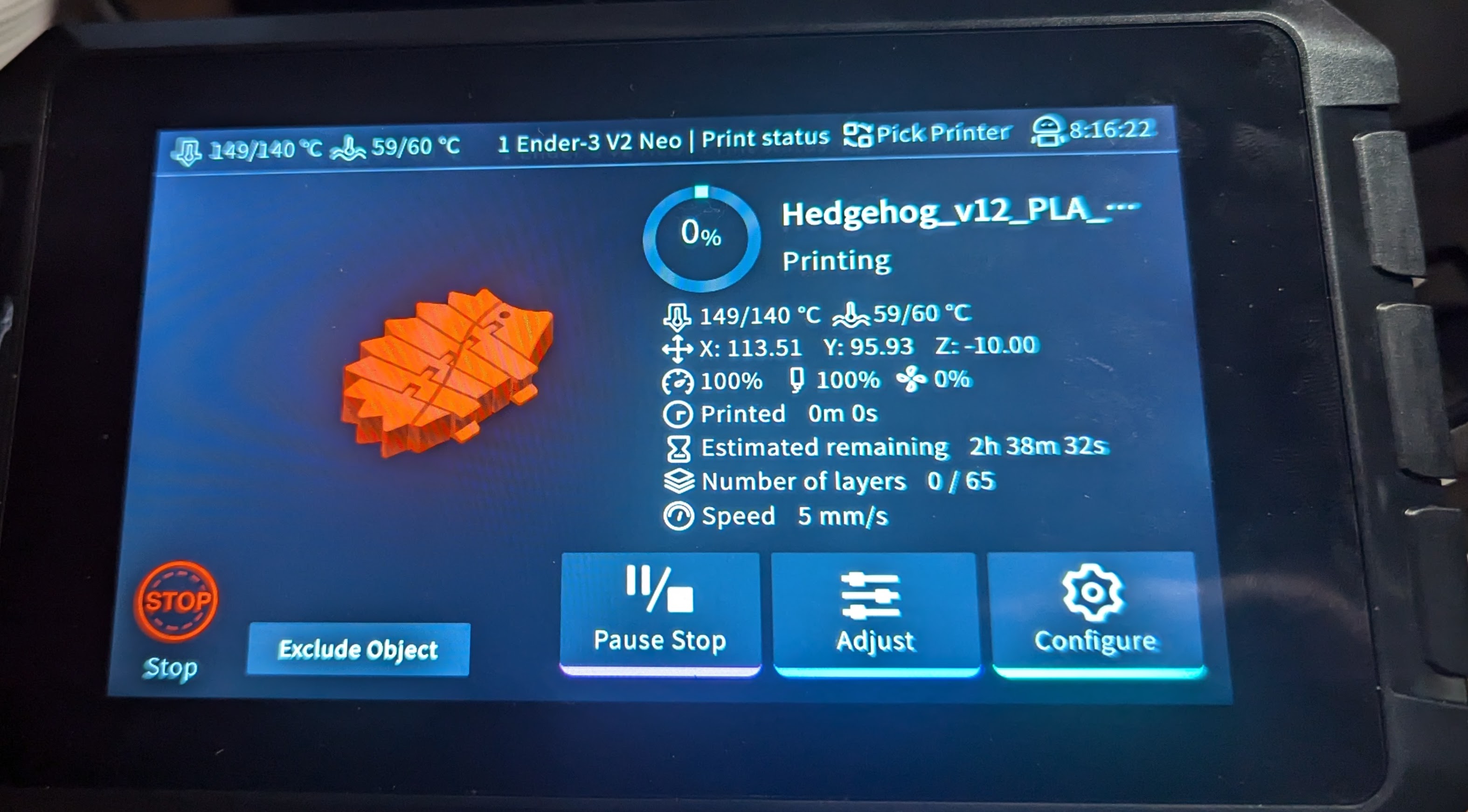
All the rest of the processing you expect to happen now runs on some Linux computer. That is very often a Raspberry Pi, but it could be a spare laptop, your desktop computer, or anything that will run a reasonable Linux install. Several vendors even sell single-board computers with touchscreens made specifically for running this part of Klipper.

However, even though a screen is nice, you don’t really need it. I’ll talk about that more later.

Continue reading “3D Printering: Klipper, The Free 3D Printer Upgrade”

Art of 3D printer in the middle of printing a Hackaday Jolly Wrencher logo

G-code Goes Binary With Proposed New Format

G-code is effective, easily edited, and nearly ubiquitous when it comes to anything CNC. The format has many strengths, but space efficiency isn’t one of them. In fact, when it comes to 3D printing in particular file sizes can get awfully large. Partly to address this, Prusa have proposed a new .bgcode binary G-code format. You can read the specification of the new (and optional) format here.

The newest version of PrusaSlicer has support for .bgcode, and a utility to convert ASCII G-code to binary (and back) is in the File menu. Want to code an interface of your own? The libbgcode repository provides everything needed to flip .gcode to .bgcode (with a huge file size savings in the process) and vice versa in a way that preserves all aspects of the data. Need to hand-edit a binary G-code file? Convert it to ASCII G-code, make your changes, then flip it right back.

Prusa are not the only ones to notice that the space inefficiency of the G-code file format is not ideal in all situations. Heatshrink and MeatPack are two other solutions in this space with their own strong points. Handily, the command-line tool in libgcode can optionally apply Heatshrink compression or MeatPack encoding in the conversion process.

In a way, G-code is the assembly language of 3D printers. G-code files are normally created when slicing software processes a 3D model, but there are some interesting tricks to be done when G-code is created directly.

CNC Plus Microscope Plus Game Controller Equals Awesome

What do you get if you strap a microscope onto a CNC and throw in a gaming controller? The answer, according to Reddit user [AskewedBox] is something kind of awesome: you get a microscope that can be controlled with the game controller for easier tracking of tiny creepy-crawlies.

[ASkewedBox] set up this interesting combination of devices, attaching their Adonostar AD246S microscope to the stage of a no-brand 1610 CNC bought off Amazon, then connected the CNC to a computer running Universal G-Code Sender. This great open source program takes the input from an Xbox game controller and uses it to jog the CNC.

With a bit of tweaking, the game controller can now move the microscope, so it can be used to track microbes and other small creatures as they wander around on the slide mounted below the microscope eating each other. The movement of this is surprisingly smooth: the small CNC and a well-mounted microscope means that there seems to be very little wobble or backlash as the microscope moves.

[Askewedbox] hasn’t finished yet, though: in the latest update, he adds a polarizing lens to the setup and mentions that he wants to add focus control to the system, which is controlled by a remote that comes with the microscope.

There are plenty of other things that could be added beyond that, though, such as auto pan and stitch for larger photos, auto focus stacking and perhaps even auto tracking using OpenCV to track the hideous tiny creatures that live in the microscopic realm. What would you do to make this even cooler?

Wood game piece being carved by a CNC mill with a hacked rotary axis

This $12 CNC Rotary Axis Will Make Your Head Spin

[legolor] brings us a great, cheap rotary axis to add to your small 3 axis CNC mills. How are you going to generate G-Code for this 4th axis? That’s the great part, and the hack, that [legolor] really just swapped the Y axis for the rotation. To finish the workflow and keep things cheap accessible to all there’s a great trick to “unwrap” your 3D model so your CAM software of choice thinks it’s still using a linear Y axis and keeps your existing workflow largely intact. While this requires an extra step in Blender to do the unwrapping, we love the way this hack changes as little of the rest of your process as possible. The Blender script might be useful for many other purposes too.

Wood game pieces carved from wood by a CNC mill with a hacked rotary axis

The results speak for themselves too! We thought the 3D printed parts were suspect in a CNC setup, but for the small scale of game pieces and milling wood, the setup is stable enough to produce a surprisingly accurate and detailed finish. If you want to try the same approach with something larger or a tougher material, [legolor] has a suggestion of a tailstock setup that’s still under $100 USD. Continue reading “This $12 CNC Rotary Axis Will Make Your Head Spin”