Resuming a print

Multiple Ways Of Recovering A Failed Print

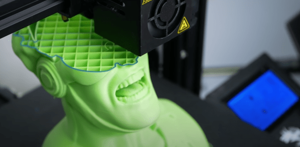
It’s a special gut-dropping, grumbly moment that most who use 3d printers know all too well. When you check on your 13-hour print, only to see that it failed printing several hundred layers ago. [Stephan] from [CNC Kitchen] has a few clever tricks to resume failed prints.

It starts when you discover your print has failed and whether the part is still attached to the bed. If it has detached, the best you can do is whip out your calipers to get a reasonably accurate measurement of how much has been printed. Then slice off the already printed section, print the remainder, and glue the two parts together. If your part is attached to your print bed and you haven’t shifted the plate (if it is removable), start by removing any blemishes on the top layer. That will make it smooth and predictable as it’s starting a new print, just on top of an existing one. Measuring the height that has been printed is tricky since you cannot remove it. Calipers of sufficient length can use their depth function, but you might also be able to do a visual inspection if the geometry is unique enough. After you load up your model in a G-Code viewer, go through it layer by layer until you find what matches what has already been printed.

The last (and perhaps most clever) is to use the printer as a makeshift CMM (coordinate measuring machine). You manually step the printer until it touches the top of the part, then read the z-axis height via a screen or M114 command. A quick edit to the raw G-Code gives you a new file that will resume precisely what it was doing before. If you can’t rehome because the head can’t clear the part, [Stephan] walks you through setting the home on your printer manually.

If all the doesn’t work, and the print is still unrecoverable, perhaps you can look into recycling the plastic into new filament.

Wire ECM built from an Ender 3

Simple Mods Turn 3D Printer Into Electrochemical Metal Cutter

We’re not aware of any authoritative metrics on such things, but it’s safe to say that the Ender 3 is among the most hackable commercial 3D printers. There’s just something about the machine that lends itself to hacks, most of which are obviously aimed at making it better at 3D printing. Some, though, are aimed in a totally different direction.

As proof of that, check out this Ender 3 modified for electrochemical machining. ECM is a machining process that uses electrolysis to remove metal from a workpiece. It’s somewhat related to electric discharge machining, but isn’t anywhere near as energetic. [Cooper Zurad] has been exploring ECM with his Ender, which he lightly modified by replacing the extruder with a hypodermic needle electrode. The electrode is connected to a small pump that circulates electrolyte from a bath on the build platform, while a power supply connects to the needle and the workpiece. As the tool traces over the workpiece, material is electrolytically removed.

The video below is a refinement of the basic ECM process, which [Cooper] dubs “wire ECM.” The tool is modified so that electrolyte flows down the outside of the needle, which allows it to enter the workpiece from the edge. Initial results are encouraging; the machine was able to cut through 6 mm thick stainless steel neatly and quickly. There does appear to be a bit of “flare” to the cut near the bottom of thicker stock, which we’d imagine might be mitigated with a faster electrolyte flow rate.

If you want to build your own Ender ECM, [Cooper] has graciously made the plans available for download, which is great since we’d love to see wire ECM take off. We’ve covered ECM before, but more for simpler etching jobs. Being able to silently and cleanly cut steel on the desktop would be a game-changer.

Continue reading “Simple Mods Turn 3D Printer Into Electrochemical Metal Cutter”

Automatic Coil Winder Gets It Done With Simple Hardware And Software

We’ve grown to expect seeing mechatronics project incorporate a standard complement of components, things like stepper motors, Arduinos, lead screws, timing belts and pulleys, and aluminum extrusions. So when a project comes along that breaks that mold, even just a little, we sit up and take notice.

Departing somewhat from this hardware hacking lingua franca is [tuenhidiy]’s automatic coil winder, which instead of aluminum extrusions and 3D-printed connectors uses simple PVC pipe and fittings as a frame. Cheap, readily available, and easily worked, the PVC does a fine job here, and likely would on any project where forces are low and precision isn’t critical. The PVC frame holds two drive motors, one to wind the wire onto a form and one to drive a lead screw that moves the form back and forth. An Arduino with a CNC shield takes care of driving the motors, and the G-code needed to do so is generated by a simple spreadsheet that takes into account the number turns desired, the number of layers, the dimensions of the spool, and the diameters of the wire. The video below shows the machine going through its paces, with pretty neat and tidy results.

Being such a tedious task, this is far from the first coil winder we’ve seen. Some adhere to the standard design language, some take off in another direction entirely, but they’re all instructive and fun to watch in action.

Continue reading “Automatic Coil Winder Gets It Done With Simple Hardware And Software”

JavaScript App Uses Advanced Math To Make PCBs Easier To Etch

We all remember the litany from various math classes we’ve taken, where frustration at a failure to understand a difficult concept bubbles over into the classic, “When am I ever going to need to know this in real life?” But as we all know, even the most esoteric mathematical concepts have applications in the real world, and failure to master them can come back to haunt you.

Take Voronoi diagrams, for example. While we don’t recall being exposed to these in any math class, it turns out that they can be quite useful in a seemingly unrelated area: converting PCB designs into easy-to-etch tessellated patterns. Voronoi diagrams are in effect a plane divided into different regions, or “cells”, each centered on a “seed” object. Each cell is the set of points that are closer to a particular seed than they are to any other seed. For PCBs the seeds can be represented by the traces; dividing the plane up into cells around those traces results in a tessellated pattern that’s easily etched.

To make this useful to PCB creators, [Craig Iannello] came up with a JavaScript application that takes an image of a PCB, tessellates the traces, and spits out G-code suitable for a laser engraver. A blank PCB covered with a layer of spray paint, the tessellated pattern is engraved into the paint, and the board is etched and drilled in the usual fashion. [Craig]’s program makes allowances for adding specific features to the board, like odd-shaped pads or traces that need specific routing.

This isn’t the first time we’ve seen Voronoi diagrams employed for PCB design, but the method looks so easy that we’d love to give it a try. It even looks as though it might work for CNC milling of boards too.

CNC Scroll Saw Add-On Cuts Beautiful Wooden Spirals

If there’s one thing that woodworkers have always been good at, it’s coming up with clever jigs and work-holding solutions. Most jigs, however, are considerably simpler and more static than this CNC-controlled scroll saw add-on that makes cool wooden spirals a snap.

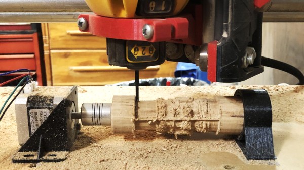
As interesting as the products of this setup are, what we like about this is the obvious care and craftsmanship [rschoenm] put into making what amounts to a hybrid between a scroll saw and a lathe. Scroll saws are normally used to make narrow-kerf cuts in thin, delicate materials, often with complicated designs using very tight radius turns. In this case, though, stock is held between centers on the lathe-like carriage. The jig uses a linear slide driven by a stepper and a lead screw to translate the workpiece perpendicular to the scroll saw blade while a geared headstock rotates it. Starting with the blade inserted into a through-hole, the saw slowly cuts a beautiful nested spiral down the length of the workpiece. An Uno, a GRBL shield, and some stepper drivers let a little G-code control the two axes of the jig.

The video below shows it in action; things do get a bit wobbly as the cut progresses, but in general the jig works wonderfully and results in some lovely pieces. At first we thought these would purely be objets d’art, but then we thought about this compression screw grinder for DIY injection molding machines and realized these wooden screws look pretty similar.

Continue reading “CNC Scroll Saw Add-On Cuts Beautiful Wooden Spirals”

CNC Hot-Wire Cutter Gives Form To Foam

Rapid prototyping tools are sometimes the difference between a project getting off the ground and one that stays strictly on paper. A lightweight, easy-to-form material is often all that’s needed to visualize a design and make a quick judgment on how to proceed. Polymeric foams excel in such applications, and a CNC hot-wire foam cutter is a tool that makes dealing with them quick and easy.

We’re used to seeing CNC machines where a lot of time and expense are put into making the frame as strong and rigid as possible. But [HowToMechatronics] knew that the polystyrene foam blocks he’d be using would easily yield to a hot nichrome wire, minimizing the cutting forces and the need for a stout frame. But the aluminum extrusions, 3D-printed connectors. and linear bearings he used still make for a frame stiff enough to give clean, accurate cuts. The addition of a turntable to the bed is a nice touch, turning the tool into a 2.5D machine. The video below details the construction and goes into depth on the toolchain [HowToMechatronics] used to go from design to G-code, including the tricks he used for making a continuous path, as well as integrating the turntable to make three-dimensional designs.

Plenty of hot-wire foam cutters have graced our pages before, everything from tiny hand-held cutters to a hot-wire “table saw” for foam. We like the effort put into this one, though, and the possibilities it opens up.

Continue reading “CNC Hot-Wire Cutter Gives Form To Foam”

Gradient Infill Puts More Plastic Where You Want It

It is always tricky setting the infill for a 3D printed part. High infill parts are strong but take longer to print, while low infill prints take less time, but are weaker internally and in danger of surface layer droop between the infill pattern. [Stephan] has a better answer: gradient infill. You can see a video below and find his Python code on GitHub.

The idea is simple enough. In most cases, parts under stress see higher stress near the surface. Putting more material there will make the part stronger than adding plastic in places where the stress is lower. [Stephan] has done finite element analysis to determine an optimal infill pattern before, but this is somewhat difficult to do. Since the majority of parts can follow the more at the edges and less at the center rule, gradient infill makes sense except for a few special cases.

Continue reading “Gradient Infill Puts More Plastic Where You Want It”