Obviously Software Defined Radio is pretty cool. For a lot of hackers you just need the right project to get you into it. Submitted for your approval is just that project. [Simon Aubury] has been using a Raspberry Pi and SDR to record video of planes passing overhead. The components are cheap and most places have planes passing by; this just might be the perfect project.
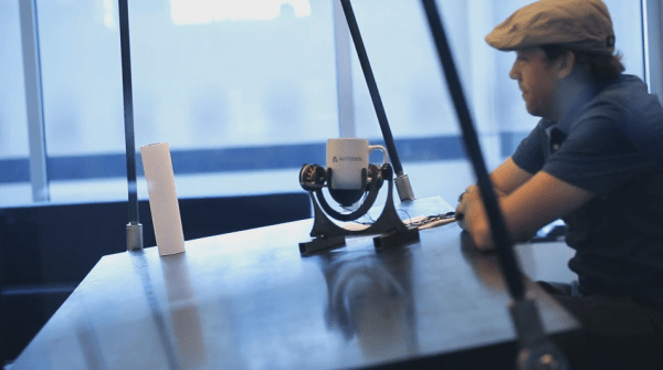
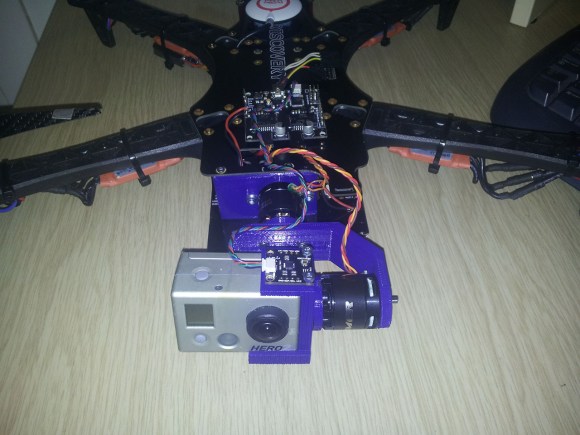
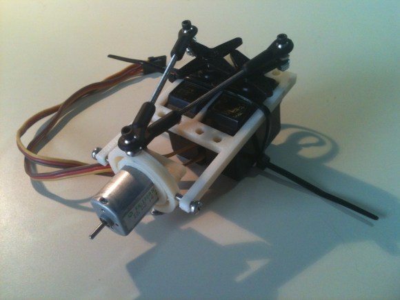
We’re not just talking static frames with planes passing through them, oh no. Simon used two hobby servos and some brackets to gimbal his Pi camera board. A DVB dongle allows the rig to listen in on the Automatic Dependent Surveillance Broadcast (ADS-B) coming from the planes. This system is mandated for most commercial aircraft (deadlines for implementation vary). ADS-B consists of positioning data being broadcast from planes using known frequencies and protocols. Once [Simon] locks onto this data he can accomplish a lot, like keeping the plane in the center of the video, establishing which flight is being recorded, and automatically uploading the footage. With such a marvelously executed build we’re certain we will see more people giving it a try.
[Simon] did a great job with the writeup too. Not only did he include a tl;dr, but drilled down through a project summary and right to the gritty details. Well done documentation is itself worth celebrating!
Continue reading “Keep Tabs On Passing Jets With Pi And SDR”