Penny And Paper Clip Heat Sinks

A bunch of audio heads over at the Head-Fi forum were discussing handy and quick heat sinking methods, leading to much speculation and conjecture. This finally prompted [tangentsoft] to take matters in his own hands and run some tests on DIY Heat Sinks.

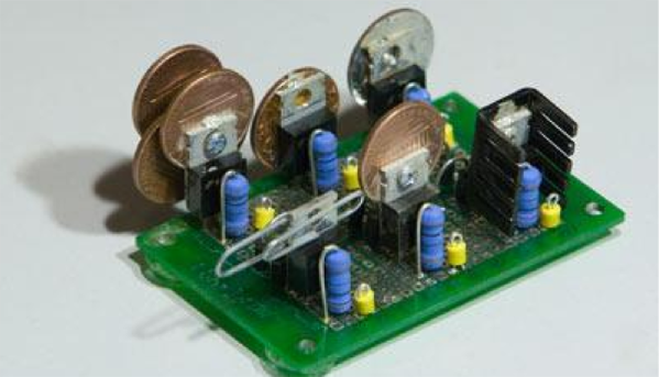
The question that sparked this debate was if a paper clip is a good enough heat sink to be used for a TO220 package. Some folks suggested copper pennies (old ones minted 1981 and earlier – the new ones are zinc with copper plating and won’t help much). [tangentsoft] built a jig to test six LM317 regulators in constant current mode set to 0.125A and 2w dissipation. The six configurations were a paper clip, a single penny bolted to the regulator, a regular Aavid TO220 heat sink, a set of 4 pennies bolted, a single penny epoxy glued and finally a single penny soldered directly to the regulator.

The results were pretty interesting. The paper clip scored better than any of the single pennies! The quad-penny and the Aavid heat sink fared above all the other configurations, and almost at par with each other. [tangentsoft] posts his review of each configurations performance and also provides details of his test method, in case someone else wants to replicate his tests to corroborate the results. He tested each configuration independently for one hour, gathering just over 10000 readings for each setup. Other nearby heat sources were turned off, and he placed strategic barriers around the test circuit to isolate it from the effects of other cooling / heating sources. He even removed himself from the test area and monitored his data logging remotely from another room. When he noticed a couple of suspect deviations, he restarted the test.

[tangentsoft] put all the data through Mathematica and plotted his results for analysis, available at this link [pdf, 2.8MB]. So the next time you want to heat sink a regulator for cheap, just hunt for Clippy in your box of office supplies. Do remember that these methods will work for only a couple of watts dissipation. If you would like to cast and build your own heat sinks out of aluminum, check out this post about DIY Aluminum heat sink casting. And if you need help calculating heat sink parameters, jump to 12:00 minutes in this video from [Dave]’s EEVBlog episode on Dummy loads and heat sinks.

Thanks to [Greg] for sending in this tip.

Behold! The Most Insane Crowdfunding Campaign Ever

Hold on to your hats, because this is a good one. It’s a tale of disregarding the laws of physics, cancelled crowdfunding campaigns, and a menagerie of blogs who take press releases at face value.

Meet Silent Power (Google translation). It’s a remarkably small and fairly powerful miniature gaming computer being put together by a team in Germany. The specs are pretty good for a completely custom computer: an i7 4785T, GTX 760, 8GB of RAM and a 500GB SSD. Not a terrible machine for something that will eventually sell for about $930 USD, but what really puts this project in the limelight is the innovative cooling system and small size. The entire machine is only 16x10x7 cm, accented with a very interesting “copper foam” heat sink on top. Sounds pretty cool, huh? It does, until you start to think about the implementation a bit. Then it’s a descent into madness and a dark pit of despair.

There are a lot of things that are completely wrong with this project, and in true Hackaday fashion, we’re going to tear this one apart, figuring out why this project will never exist.

Continue reading “Behold! The Most Insane Crowdfunding Campaign Ever”

a black aluminum heatsink with fins on a green matt

Hacking Manufacturing: Ordering A Custom Heatsink From China

Building a one-off hack is fun. But what happens when people like your hack so much they want to buy it? As many of us have discovered, going from prototype to product can be a frustrating, tedious, and often expensive process. [Nick] at Arachnid labs has documented the process of manufacturing a custom heatsink in China.

While designing the Re:Load Pro, [Nick] discovered that there were no enclosures with integrated heatsinks which suited his application. Rather than design an entire case from scratch, [Nick] used an aluminum extrusion. This is a common technique in the electronics world, and literally thousands of extrusion profiles are available. The problem was the heatsink. Only a custom part would fit the bill, so [Nick] created a CAD drawing detailing his design. Much like the case, the heatsink was an aluminum extrusion. The custom nature of the heatsink meant that [Nick] would need to pay mold/tooling costs as well as satisfy minimum orders.

Continue reading “Hacking Manufacturing: Ordering A Custom Heatsink From China”

Can’t Stand Your Noisy Fan? Here’s A Plan, Man

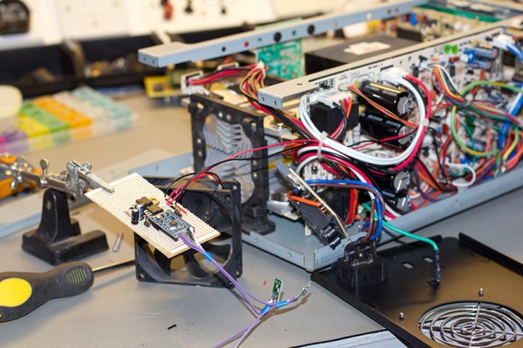
[Brian] adores his GW Instek GPC-1850D power supply, but it’s annoyingly loud and disruptive to his audio projects. The thing works great, so he decided to regulate the fan’s speed based on usage level to save his sanity.

Once [Brian] got under the hood, he found that it actually has four separate heatsinks: one for the bridge rectifiers and one for each power transistor on the three output channels. The heatsinks are electrically and thermally isolated from each other and change temperature based on the channel being used.

[Brian] and his associates had several Microchip MCP9803 temperature sensors kicking around the lab from previous projects, so they put one on each heatsink. The great thing about these is their address selection pins which let all four of them sit together on the I²C bus to Arduinoville. Each sensor is insulated and clamped to its heatsink with a piece of meccano and a dab of thermal paste.

[Brian] used an Arduino Mini and built the circuit on stripboard. The fan runs at 24V, so he’s sharing that with the Arduino through a 7805. He controls the speed of the fan with PWM from the Arduino fed through a MOSFET. The Arduino reads from each sensor and determines which one is hottest. [Brian] wanted the fan to run at all times, so he set a base speed of 20%. When the heatsinks reach 30°C/86°F, the fan speed is increased to 40%. After that, the speed increases at 5°C/9°F intervals until it reaches max speed at 65°C/149°F.

You can grab the code and schematic from [Brian]’s repo. If you want to study your heatsinks, build this heatsink tester first.

Heatsink Tester Shows Thermal Resistance Isn’t Futile

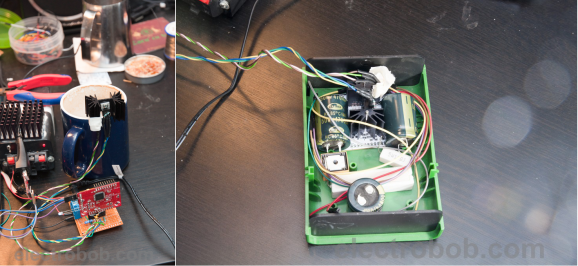
[Bogdan] knows that it’s hard to model the cooling needs of any given project. It’s important to know how much heat a system can dissipate given the housing material, airflow opportunity, and the proximity of neighboring components. Inspired by an aluminium-walled enclosure that allows for mounted transistors, he devised and built a heatsink tester.

He’s using an ATXMEGA32A4U, a temperature sensor, and a IRF540 MOSFET. A specific power is dissipated across the transistor, and the temperature sensor measures the heatsink as close as possible to the transistor. Through the serial connection, he gets back the supply voltage, current, calculated power, DAC set, temperature, and calculated thermal resistance in the terminal.

[Bogdan]’s tester assumes that it is reading the ambient temperature, so the circuit needs to warm up first. He found that an hour is generally long enough to reach this point. He also found that the system exhibits high thermal inertia, so it regulates the DAC output based on the dissipated power.

Passively Cooled Computer

This came in on the tipline: [Ville ‘Willek’ Kyrö] wanted to build a fully passively cooled computer. That means no fans at all. He started with scrap aluminum heatsinks, ripped apart a cpu heatsink to get the copper heat pipes, and began surrounding the boards with heatsinks to form a case. Cooling down the powersupply was the hardest part, as it did not lend itself to the flat surfaces of heatsinks. Any passive case with powerful components will inevitably be huge and heavy; this one weighs over 20 kg. He says, “It might not have been worth it, but it sure was weird watching the computer boot up with no sound at all”.