Humidity Activated Bathroom Fan

bathroom humidifier

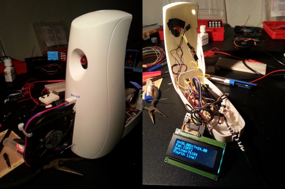
[Andrea] recently moved into an apartment with a few of his friends. Unfortunately the bathroom lacks one of the most important things — A fan. Or at least a window!

Using the case of an air freshener, a simple DHT11 Humidity/Temperature sensor, an LCD, a 12V fan, and ATmel328 microcontroller, he created this handy gadget.

When the humidity in the bathroom passes the 50% threshold, an LED flashes to prompt the user to open the door. After a short delay, one of the transistors flips causing the moist air to circulate out of the room.

We’re surprised the little 12V fan is powerful enough to clear the room, but apparently it helps a lot and can clear the room in less than 20 minutes.

To see it in action, stick around after the break.

Continue reading “Humidity Activated Bathroom Fan”

Building A Replacement For A Broken Dehumidifier Controller

dehumidifier-replacement-controller

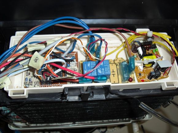
We’ve thought of doing a project like this ourselves as the dehumidifier we ordered online runs the fan 24/7 no matter what the humidity conditions. But it wasn’t that [Davide Gironi] was unhappy with the features on his unit. It’s that the dehumidifier controller stopped working so he replaced it with one of his own design. The original humidity sensor was mechanical and simply broke. He used an AVR along with a humidity and frost sensor to get the appliance up and running again.

A DHT22 humidity sensor is polled by the ATmega8 chip and compared to the user-adjustable trimpot value. If it is above that threshold the unit is switched on using one of the relays seen in the image above. The one problem you have to watch out for when using compressor cooled appliances is ice accumulation on the radiator. [Davide] uses a thermistor for temperature feedback, switching the compressor off when it gets below 7C and turning it back on again when it is above 12C.

The replacement still uses the reservoir sensor and indicator LEDs. We, however, would recommend using the watchdog timer on the chip to ensure that it is reset if something goes wrong in the code.

Weather Station Graphs History On Webpage

weather-station

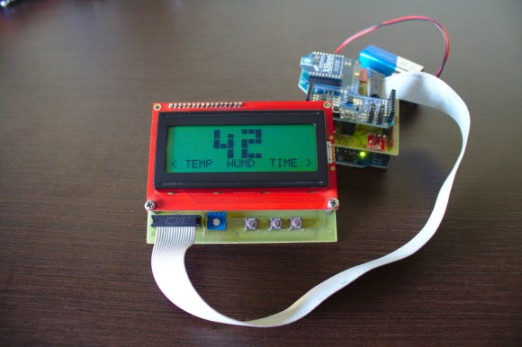
Kudos go out to [Jose] for his work getting so many different components to talk to each other in this Arduino weather station that using a Raspberry Pi to display the data online.

The components shown above make up the sensor package. There’s an Arduino with a custom shield that interfaces the barometric pressure sensor, real-time clock chip, a digital temperature sensor, and a humidity sensor. On top of that shield is an XBee shield that lets this push data back to the base station. [Jose] also rolled in an LCD character display and a few buttons so that the user may view weather data without heading to the web.

A Raspberry Pi board makes up the other half of the XBee pair. It harvests the incoming data from the radio module using a USB to Serial converter cable. You can see the data log on the webpage linked above. Just choose the “LIVE” menu option and click on “Daily” to get a better overview of humidity and pressure changes.

Sensor Array Tries To Outdo The Other Guys

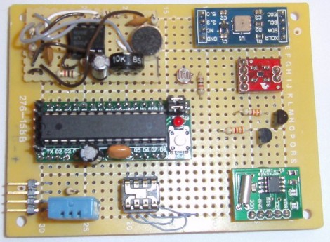
The team over at the Louisville Hackerspace LVL1 is not going to be outdone when it comes to collecting environmental data. They put together this Frankenstein of sensor boards that lets you collect a heap of data showing what is going on around it.

At the center-left a small Arduino clone is responsible for collecting the data. Data storage is not talked about on their write-up, but if that’s an ATmega328 chip you should be able to work out an easy way to store data on the 1k of internal EEPROM. If that’s not enough, there is an I2C bus included on the board making it easy to add a compatible EEPROM.

The sensor on the bottom left should look familiar. It’s a DHT11 temperature and humidity sensor we’ve seen popping up in projects lately. But wait, there’s also a TMP102 temperature sensor; but that’s not the end of it. A BMP085 pressure sensor also includes a third temperature sensing option. Want to see when the lights go on in the room? There’s a CdS sensor and a TSL230R Lux sensor for that. An op-amp circuit can measure the sound level in the room via one of the Arduino’s ADC pins. And finally, an RTC board is used for time stamping the data.

Obviously this is overkill, and we’re sure it’s meant as a test platform for various sensors. All of them have been mounted on the protoboard and wired up using the point-to-point soldering method.

DHT11 Humidity And Temperature Sensor Package

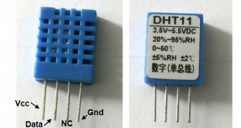
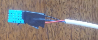
Temperature and humidity measurements are a nice addition to many hobby projects. But [Rajendra Bhatt] makes the point that many of these sensors have a price tag that is well above what most hobbiests are willing to spend. He decided to take an in-depth look at the DHT11 sensor; which you can get your hands on for under $3 if you know where to look.

The four-pin device uses a 1-wire protocol. [Rajendra] discusses the ins and outs of the communications, demonstrating the part using a PIC 16F628. It’s a snap to connect to your project, requiring VCC, GND, and a pull-up resistor on the single data line. We’ve already seen it used on at least one project, and hope to see more of this little guy in your own hacks.

Now we found this part listed on eBay for less than $3 (buy it now price including shipping… how can they do that?). But Octopart didn’t come up with any options. If you know how to get this through traditional parts suppliers let us know in the comments.

Electronic Bird House Monitoring Goes A Few Steps Further

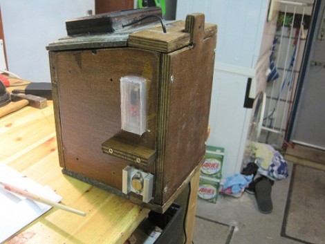
[Stephen Albers] offers his avian friends a lot of extras with this electronically monitored bird house. This will not only give you a look at what’s going on inside, but provide a source for several other bits of data as well.

First off, a camera has been mounted to the underside of the roof. This looks down on the nesting area and features night vision so that you can peek in any time day or night. He used a WiFi webcam that operates separately from the other electronics.

With the remainder of the setup he is able to harvest temperature and humidity data inside, temperature outside, force on the bottom of the house (although this turned out to be less useful than anticipated), and a in-and-out count for the doorway provided by an IR transmitter/receiver pair.

This offers quite a bit more than the last bird house project we saw. That one also left a lot to be desired as far as protecting the electronics. [Stephen] didn’t skip on that kind of protection. Most of the electronics are housed in an acrylic chamber in the base of the house. The sensors find themselves nestled in plastic enclosures, although some work needs to be done to ensure that the temperature and humidity sensors will still function correctly with this setup.

Lolo’s (perfect Moment) Alarm Clock

[youtube http://www.youtube.com/watch?v=CphsgESZGcE&feature=player_embedded%5D

It seems everybody has a different interpretation of the perfect alarm clock. [Loic Royer’s] alarm clock is not the loudest, or the smartest, but does have some interesting features. By monitoring several environmental factors like temperature, air quality, humidity, dew point, and your own sleep patterns, this alarm clock can determine the best moment in the morning to wake you up.

The main sensor is a wireless accelerometer with the theory being: the more you move in your sleep, the closer you are to a conscious state. The other sensors assist in picking the perfect moment, and awaken you with the sound of birds chirping.

For now all we have is the source code and the list of hardware, but for anyone wanting to try, a circuit diagram wouldn’t be too hard to figure out on your own. Check after the rift for some more videos. Continue reading “Lolo’s (perfect Moment) Alarm Clock”