Driving A Salvaged LCD

[bill2009] wanted to reuse some common seven segment LCDs, but the question was how to drive them. Armed with a couple application notes from [Microchip] and [Atmel], an oscilloscope and an Arduino, he has made a proof of concept which shows its not super hard to drive those little reflective LCDs that so many devices have.

First finding out that these things are indeed multiplexed, he went on to what is needed to drive them, which is about +-2 volts difference from the backplane, next up was to find a donor, which he found readily at Staples, in the form of a “clocky” style run away alarm clock.

After poking around watching what signals do to the different segments on the LCD he whipped up a little circuit to control the display from the Arduino. The positive and negative voltages the segments require are made possible by the use of a set of pull down resistors, and switching pin modes on the micro controller.

These small type segmented LCDs are everywhere, and being able to use them is a big bonus.

Laptop LCD Reused In Beagleboard Project

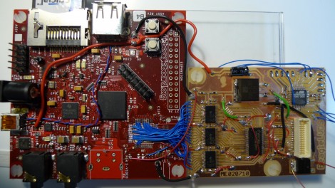
This daughterboard lets [Matt Evans] drive a laptop LCD using a Beagleboard. Apparently the Beagleboard gained a VGA header when it moved to revision C but [Matt’s] working with revision B4 which is why he had to do all of that ninja soldering with the blue wires. The driver board itself is a thing of beauty, hosting a DS90C363 LVDS serialiser as well as some buffer chips that handle level conversion for it. He’s also included an ATmega48 so that he has some options for future improvements.

The LCD is mounted in a custom acrylic case, with Beagleboard and driver board taped to the back of it. There’s RS232 and a USB hub which opens up the possibility of using a WiFi dongle for communications. So far he doesn’t have much functionality other than displaying images on the screen but there is some talk about using a touchpad for control. We’d love to see a touchscreen overlay, transforming the build into a proper ARM-based tablet.

Charging Timer For R/C Batteries

arduino_controlled_socket

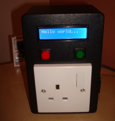
Santa brought [Quinten’s] son a shiny R/C truck for Christmas, but this new toy had one drawback – its batteries could only be connected to the charger for a maximum of 6 hours, lest he turn his house into a pile of smoldering ash.  With grave warnings from the manufacturer dancing in his head, he searched around for a timer that would allow him to cut power to the battery after charging for its allotted time.  Coming up empty, he decided to create his own timed electric socket regulated by an Arduino he had sitting around.  He grabbed a project box and wired up a nice looking socket timer, complete with an LCD status display.  To make things easy for his son, he added two buttons to the front of the controller – one for selecting the amount of charging time, and one to set the timer in motion.  As with his previous hacks, [Quinten] has provided plenty of documentation in the form of pictures, code, and even a video of the timer in action.

Bringing An LCD Viewfinder Back To Life

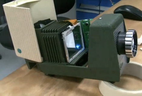
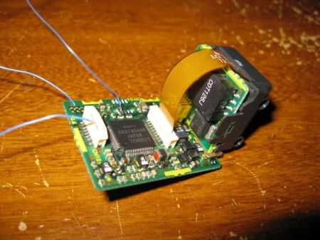
[Foobarbob] posted a pretty simple job of bringing an LCD viewfinder back to life. He doesn’t specify what was wrong, but since he replaced the backlight, we’re guessing that was the main issue.  It was pulled off of a JVC camcorder. The camcorders with LCD viewfinders are getting more and more common at garage sales, so we’re surprised we don’t see more of these used. [Foobarbob] cracked it open, traced out the power lines and replaced the backlight with an LED and a makeshift diffuser made from a bottle cap. His results look great, we could see this being perfect for an HMD, or possibly a home made VR helmet.

Key Chain LCD As Screen For A Dockstar

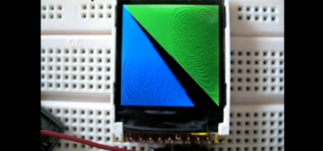
[Peter Gunn] added an LCD screen to his Dockstar. Now that we think of it, this really shouldn’t be all that hard since the Dockstar can run a Linux kernel and it has USB ports. [Peter] took inspiration from [Sprite_TM’s] key chain LCD4Linux hack that we looked at many moons ago. He used a cheap Coby DP182 digital picture frame that can be picked up for less than $5 used. A bit of firmware hacking and LCD4Linux has no problem pushing images to the device via USB. [Peter’s] setup refreshes the screen at one frame per second, but if all you need is a bit of feedback from the otherwise headless system this is a great solution.

[Thanks Mikka]

Girltech. Sugar Cubes. Monocrome LCD

We’ve seen these little toys called “sugar cubes” by GirlTech around for a while now. They are a toy block, with an LCD on the front and they respond to movement, button presses and they interact with each other if you stack them up. We’re just as curious as anyone else about their internals, but maybe not quite curious enough to rush out and buy one. Luckily, we don’t have to as [Joby] has done it for us and documented what he found. While it may be lacking in extreme detail, at least our curiosity is somewhat satiated.
We can see that it has a 16×16 LCD, an unknown chip hidden under an epoxy blob as usual. To determine what character is shown, you can bridge one of 4 spots on the PCB, though he has only managed to switch to a little ninja and a question mark. Does anyone have any brilliant ideas on a project for these?

Diving Deep Into The Game Boy LCD Protocol

[Craig] wanted to make the original Game Boy LCD screen do his bidding so he sniffed out the data protocol that it uses. We were amused when he mentions that there’s an army of people out there looking to build pointless crap as part of a hobby. Guilty. And he goes on to outline why this LCD screen is a great resource for hobbiests.

As you can see in the pinout above, it uses 5V logic, with a 4 MHz data clock. These traits are both very friendly to a wide range if inexpensive microcontrollers. If you know how to address the display it should be very easy to use. Furthermore, the low pin count is thanks the to a 4-shade grayscale screen, limiting the data pins to just two. [Craig] hooked up his Saleae Logic probe to capture communications and walks us through what he discovered. During this process he proved to himself that he had figured out the protocol by exporting captured data from the logic probe and reassembling it into an image on his computer.