LTSpice For Radio Amateurs (and Others)

We don’t think [VK4FFAB] did himself a favor by calling his seven-part LTSpice tutorial LTSpice for Radio Amateurs. Sure, the posts do focus on radio frequency analysis, but these days lots of people are involved in radio work that aren’t necessarily hams.

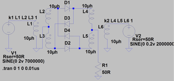
Either way, if you are interested in simulating RF amplifiers and filters, you ought to check these posts out. Of course, the first few cover simple things like voltage dividers just to get your feet wet. The final part even covers a double-balanced mixer with some transformers, so there’s quite a range of material.

Continue reading “LTSpice For Radio Amateurs (and Others)”

A Spicy Regenerative Reciever

We recently posted a three-part series about using LTSpice to simulate electronic circuits (one, two, three). You might have found yourself wondering: Can you really simulate practical designs with the program? This quick analysis of [QRP Gaijin’s] minimalist regenerative receiver says “yes”.

Continue reading “A Spicy Regenerative Reciever”

Transforming Spice

Spice is a circuit simulator that you should have in your toolbox. While a simulator can’t tell you everything, it will often give you valuable insight into the way your circuit behaves, before you’ve even built it. In the first installment of this three-part series, I looked at LTSpice and did a quick video walkthrough of a DC circuit. In the second, I examined two other parts of Spice: parameter sweeps and AC circuits. In this final installment, I want to talk a bit more about real-world component performance and also look at modeling transformers.

Recap

lowpasssLast time we looked at a low pass filter, but it wasn’t practical because the components were too perfect. Only in simulation do voltage sources and wires have zero resistance. There was no load resistance either, which is unlikely. Even an oscilloscope probe will load the circuit a little.

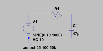
The resulting AC analysis showed a nice filter response that was flat to about 1 kHz and then started roll off as the frequency increased. Suppose the source had an 8 ohm series resistor. How does that change the circuit response?

Continue reading “Transforming Spice”

Spice Power

Spice is a circuit simulator that you should have in your toolbox. While a simulator can’t tell you everything, it will often give you valuable insight into the way your circuit behaves, before you’ve even built it. In the first installment of this three-part series, I looked at LTSpice and did a quick video walkthrough of a DC circuit. This time, I want to examine two other parts of Spice: parameter sweeps and AC circuits. So let’s get to it.

schem2In the first installment, I left you with a cliffhanger. Namely the question of maximum power transfer using this simple circuit. If you run the .op simulation you’ll get this result:

--- Operating Point ---
V(n001): 5 voltage
I(R1): 0.1 device_current
I(V1): -0.1 device_current

The power in R1 (voltage times current) is .5 W or 500 mW if you prefer. You probably know that the maximum power in a load occurs when the load resistor is the same as the source resistance. The Rser parameter sets the voltage source’s internal resistance. You could also have created a new resistor in series with V1 and set it explicitly.

Continue reading “Spice Power”

Adding Spice To Your Workbench

Most of us didn’t fight in World War II, drive a race car, or fly the Space Shuttle. But with simulation, you can experience at least some of what it would be like to do those things. Granted, playing Call of Duty isn’t really the same as going to war. No matter what you are simulating, it only goes so far. However, you can get a lot of value from a simulation. I’d bet the average kid who has played Call of Duty knows more about WWII locales and weapons than my high school history teacher.

When it comes to electronics, simulation is an excellent way to get insight into a circuit’s operation. After all, most circuits operate in the abstract–you can’t look at an audio amplifier and see how it works without a tool like a scope. So simulation, when done well, can be very satisfying. You just have to be careful to remember that it isn’t always as good as the real thing.

That’s Spicy

One of the best-known electronics simulators is Spice, which Berkeley created in 1973. In its original form, you had to punch cards that described your circuit and the analysis you wanted to perform. Modern PC versions sometimes replace the deck of cards with a text file. The best modern versions, though, give you a GUI that allows you to draw a schematic and then probe it to see the results.

There are several paid and free versions of Spice (and other simulators) that include a GUI. One of the best for a casual user is the free offering from Linear Technology called LTSpice.

Linear makes LTSpice available and populates it with models for their devices in the hopes you’ll buy components from them. However, the software is entirely usable for anything, and it has a powerful set of features. Linear produces the software for Windows, but I can attest that it runs just fine under Wine on Linux. The Web site will invite you to register, but you don’t have to if you don’t want to.

Continue reading “Adding Spice To Your Workbench”

Using LTSpice To Measure Total Harmonic Distortion

Audiophiles spend a lot of time and effort worrying about audio specs like Total Harmonic Distortion (THD). Makes sense, because THD affects the quality of audio reproduction. However, THD can also affect interference from radio signals and even losses in power transfer systems. A simplified definition is the THD is the ratio of the sum of the power of all harmonic frequencies to the power of the fundamental frequency.

If a circuit produced a perfect sine wave, there would be no harmonics. There are many ways to measure THD in practice, but [Michael Jackson] has an interesting video showing how he easily visualizes THD using LTSpice. Assuming you already have the system in question in LTSpice (or you could use another simulation tool, if you prefer) it is fairly straightforward.

Continue reading “Using LTSpice To Measure Total Harmonic Distortion”

Schematic for a boost converter based on the ATtiny MCU

An ATtiny Boost Converter

This schematic is all you need to build your own voltage converter. [Lutz] needed a converter that could boost 5 V to 30 V to power a string of LEDs. The solution was to use low cost ATtiny85 and some passive components to implement a boost converter.

This circuit follows the classic boost converter topology, using the ATtiny85 to control the switch. The 10 ohm resistor is fed back into the microcontroller’s ADC input, allowing it to sense the output voltage. By measuring the output voltage and adjusting the duty cycle accordingly, the circuit can regulate to a specified voltage setpoint.

A potentiometer is used to change the brightness of the LEDs. The software reads the potentiometer’s output voltage and adjusts the voltage output of the circuit accordingly. Higher voltages result in brighter LEDs.

Of course, there’s many other ways to implement a boost converter. Most practical designs will use a chip designed for this specific purpose. However, if you’re interested in rolling your own, the source and LTSpice simulation files are available.