Fail Of The Week: How I Killed The HiPot Tester

Have you ever wired up a piece of test equipment to a circuit or piece of equipment on your bench, only to have the dreaded magic smoke emerge when you apply power? [Steaky] did, and unfortunately for him the smoke was coming not from his circuit being tested but from a £2300 Clare H101 HiPot tester. His write-up details his search for the culprit, then looks at how the manufacturer might have protected the instrument.

[Steaky]’s employer uses the HiPot tester to check that adjacent circuits are adequately isolated from each other. A high voltage is put between the two circuits, and the leakage current between them is measured. A variety of tests are conducted on the same piece of equipment, and the task in hand was to produce a new version of a switch box with software control to swap between the different tests.

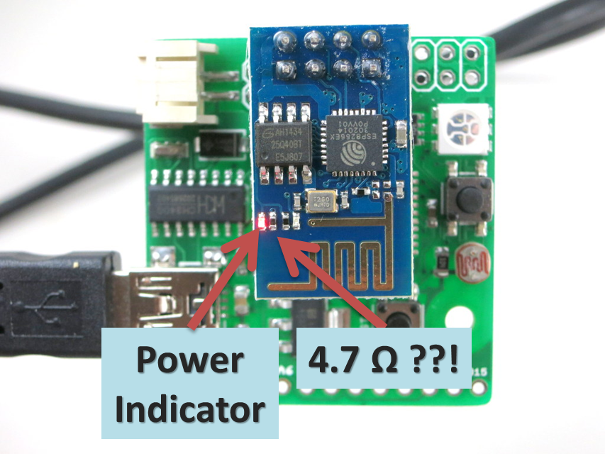
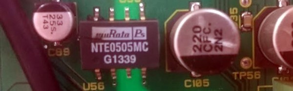
This particular instrument has a guard circuit, a pair of contacts that have to be closed before it will proceed. So the switch box incorporated a relay to close them, and wiring was made to connect to the guard socket. At first it was thought that the circuit might run at mains voltage, but when it was discovered to be only 5V the decision was made to use a 3.5mm jack on the switch box. Inadvertently this was left with its sleeve earthed, which had the effect of shorting out a DC to DC converter in the HiPot tester and releasing the smoke. Fortunately then the converter could be replaced and the machine brought back to life, but it left questions about the design of the internal circuit. What was in effect a logic level sense line was in fact connected to a low current power supply, and even the most rudimentary of protection circuitry could have saved the day.

We all stand warned to be vigilant for this kind of problem, and kudos to [Steaky] for both owning up to this particular fail and writing such a good analysis of it.

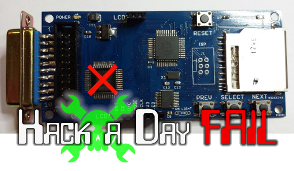
Our Fail Of The Week series has plenty to entertain the reader who is not of a nervous disposition. This isn’t the first fail to feature a suspect bit of connector wiring, not an unexpected short or even some magic smoke.

circuit board

Driving A Brushless DC Motor Sloooooooowly

Driving a brushless DC (gimbal) motor can be a pain in the transistors. [Ignas] has written up a nice article not only explaining how to do just this with an Arduino, but also explaining a little bit on how the process works. He uses a L6234 Three Phase Motor Driver, but points out that there are other ways to interface the BLDC motor with the Arduino.

warningA warning is warranted – this is not for the faint of heart. You can easily destroy your microcontroller if you’re not careful. [Ignas] added several current limiting resistors and capacitors as advised in the application note (PDF warning) to keep things safe.

Everything worked well at high speeds, but for slower speeds the motor was choppy. [Ingus] solved this riddle by changing over to a sine wave to drive the motor. Instead of making the Arduino calculate the wave, he used a look up table.

Be sure to check out his blog for full source and schematics. There is also a video demonstrating just how slow he can make the motor move below.

Continue reading “Driving A Brushless DC Motor Sloooooooowly”

Faulty ESP8266s Release Smoke, Then Keep Working?

[Ray] is in a bit of a pickle. All appeared well when he began selling an ESP8266-based product, but shortly thereafter some of them got hot and let the smoke out. Not to worry, he recommends ignoring the problem since once the faulty components have vaporized the device will be fine.

The symptom lies in the onboard red power indicator LED smoking. (Probably) nothing is wrong with the LED, because upon testing the batch he discovered its current limiting resistor is sometimes a little bit low to spec. Off by a hair of, oh, call it an even 1000x.

HAD - HotESPY3Yep, the 4700 ohm resistor is sometimes replaced with a 4.7 ohm. Right across the power rail. That poor little LED is trying to dissipate half a watt on a pinhead. Like a sparrow trying to slow a sledgehammer, it does not end well. Try not to be too critical, pick ‘n place machines have rough days now and then too and everyone knows those reels look practically the same!

The good news is that the LED and resistor begin a thermal race and whoever wins escapes in the breeze. Soon as the connection cuts the heat issue disappears and power draw drops back to normal. Everything is fine unless you needed that indicator light. Behold – there are not many repairs you can make with zero tools, zero effort, and only a few seconds of your time.

[Ray] also recommends measuring and desoldering the resistor or LED if you are one of the unlucky few, or, if worst comes to worst, he has of course offered to replace the product too. He did his best to buy from authentic vendors and apologizes to the few customers affected. As far as he knows no one else has had this problem yet so he wanted to share it with the community here on Hackaday as soon as possible. Keep an eye out.

If you have never seen smoke ISO9001-certified electronics repair before, there is a short video of this particular disaster upgrade caught live on tape after the break.

Continue reading “Faulty ESP8266s Release Smoke, Then Keep Working?”

Fail Of The Week: CPLDs That Release Blue Smoke

The card you see above is a floppy drive emulator for Macintosh. [Steve Chamberlain] has been hand assembling these and selling them in small runs, but is troubled by about a 4% burn-out rate for the CPLD which has the red ‘X’ on it. He settled into figure out what exactly is leading to this and it’s a real head-scratcher.

He does a very good job of trouble-shooting, starting with a list of all the possible things he thinks could be causing this: defective part, bad PCB, bad uC firmware, damage during assembly, solder short, tolerance issues, over-voltage on the DB connector, or bad VHDL design. He methodically eliminates these, first by swapping out the part and observing the exact same failure (pretty much eliminates assembly, solder short, etc.), then by measuring and scoping around the card.

The fascinating read doesn’t stop with the article. Make sure you work your way through the comments thread. [Steve] thinks he’s eliminated the idea of bad microcontroller code causing damage. He considers putting in-line resistors on the DB connector but we wonder if clamping diodes wouldn’t be a better choice (at least for testing purposes)? This begs the question, why is he observing a higher voltage on those I/O lines during power-up? As always, we want to hear your constructive comments below.


2013-09-05-Hackaday-Fail-tips-tile
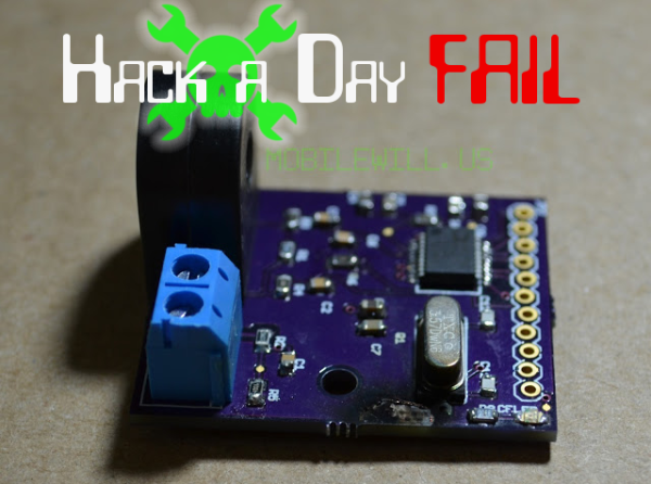
Fail of the Week is a Hackaday column which runs every Wednesday. Help keep the fun rolling by writing about your past failures and sending us a link to the story — or sending in links to fail write ups you find in your Internet travels.

Fail Of The Week: Inaugural Edition

We’re sure you’ve all been waiting on the edge of your seats to see whose project makes it as the first Hackaday Fail of the Week. Wait no longer, it’s [Mobile Will] with his woeful tale about monitoring AC current usage.

He had been working on a microcontroller actuated mains outlet project and wanted an accurate way to measure the AC current being used by the device connected to it. The ADE7753 energy metering IC was perfect for this so he designed the board above and ordered it up from OSH Park. After populating the components he hooked it up to his Arduino for a test run, and poof! Magic blue smoke arose from the board. As you’ve probably guessed — this also fried the Arduino, actually melting the plastic housing of the jumper wire that carried the rampant current. Thanks to the designers of the USB portion of his motherboard he didn’t lose the computer to as the current protection kicked in, requiring a reboot to reset it.

We can’t wait to hear the conversation in the comments. But as this is our first FotW post we’d like to remind you: [Mobile Will] already knows he screwed up, so no ripping on his skills or other non-productive dibble. Let’s keep this conversation productive, like what caused this? He still isn’t completely sure and that would be useful information for designing future iterations. Update: here’s the schematic and board artwork.

We’ve got a bit more to share in this post so keep reading after the break.

Continue reading “Fail Of The Week: Inaugural Edition”

Exploding An AVR

Unfortunately [manekinen] wrecked a couple of AVRs during his tinkering. Not letting this get him down he decided to blow them up to see what would happen. In exchange for their precious magic smoke the AVRs revealed a good portion of their silicon die.

While the details are a little sparse it seems like he hooked them up to a high (and possibly reverse) source to blow open the chips casing. From the pictures it looks like he was able to reveal some of the flash or SRAM (the big multi colored rectangles) and what could possibly be the power supply. Be sure to checkout the videos after the break for some silicon carnage.

Continue reading “Exploding An AVR”