Get yourself a decent stereo inspection microscope, preferably optical. Something that can magnify from maybe 4x to 40x is fine, anything outside this range is icing on the cake. Some people claim they’re fine with a minimum of 10x, but if you go there, you’re going to need a reducing lens eventually. Either way, get one, and you’ll thank me.
How do I know this? I finally caved in and bought one about two years ago now, and while it’s not something I use daily, it’s something that I use at least once a month and for which there is simply no substitute.
This is Hackaday, so a lot of you will be thinking “inspection scope = fine-pitch soldering” and you’re not wrong. With clearance of 10 cm or more, and a slab of sacrificial optical glass (“neutral density filter”) to protect the optics from tarry flux fumes, a stereo scope at 4x makes even the fiddliest solder joints possible. Good lighting, and sharp tweezers are also a must, of course. That’s what got me in the door.
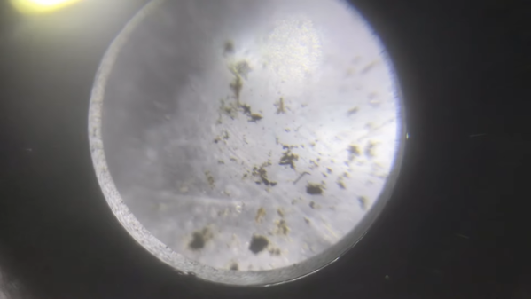
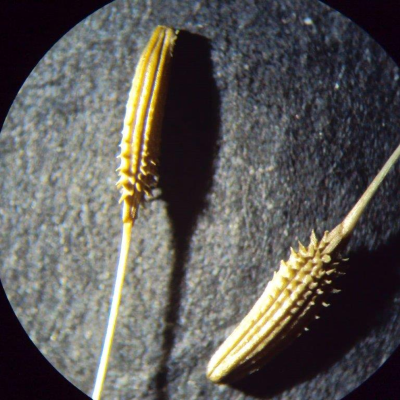 But that’s the half of it, or less. When my scope was new to me — it hasn’t been “new” since the late 1980s — we spent a whole rainy Sunday afternoon microscoping whatever would fit under the lens. Grains of salt, blades of grass, all manner of bugs living and otherwise, shells, skin, textiles. Everything is cooler under the microscope.
The event that triggered this article wasn’t my son’s school project this week to photograph dandelion seeds. Nope, today my wife found a bug in the basement; to the microscope! And with a very quick and unfortunately very positive identification, we now know that we have to strain all of our flour for bread beetles and pitch whichever bags they came in with. Hooray!
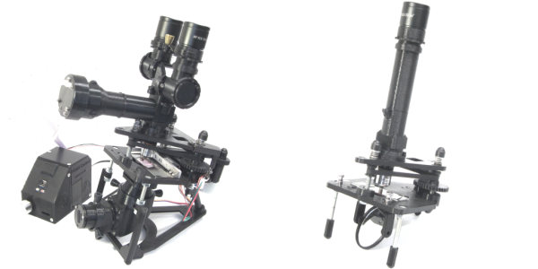
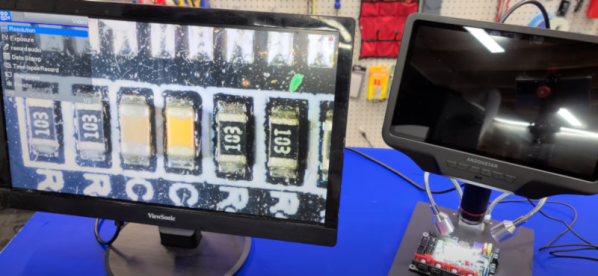
The inspection scope was intended for the soldering bench, but has found general use as an irreplaceable household tool. While I admittedly also intended to use it to lure my son into science, the real fight over scope time has been with my wife. And that’s why you want an optical scope instead of one that’s tethered to a monitor — as a general-purpose tool, portability is paramount. No menu diving, no power source, and anyone can just grab it and go.
Convinced? Ready to pull out your wallet? Microscopes are like cars. You can spend as much as you’d like on one, the cheapest will cause you nothing but pain and suffering, and the difference between the mid-range and high-end is full of diminishing returns. Buying used, especially if you can kick the metaphorical tires, can be a great bargain, and a high-end used scope will hold its value a lot better than a new budget model. Just around $200 is a sweet spot new and $300-$400 will get you the top of the line from yesteryear if you shop around. That’s not cheap, but if you’re the microscope type, it’s easily worth it. Trust me.