Making A Homemade Stephen Hawking

It isn’t easy communicating when you have any form of speech impairment. In such cases, a Speech-generating device (SGD) becomes essential to help you talk to the world. When coupled with other ailments that limit body movement, the problem becomes worse. How do you type on a keyboard when you can’t move your hands, and how do you talk when your voice box doesn’t work. Well known Scientist Stephen Hawking has been battling this since 1985. Back then, it took a lot of hardware to build a text entry interface and a text to speech device allowing him to communicate.

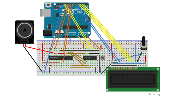
But [Marquis de Geek] did a quick hack using just a few parts to make a Voice Box that sounds like Stephen Hawking. Using an arcade push button to act as a single button keyboard, an Arduino, a 74HC595 shift register, a 2-line LCD, and the SP0256 hooked to an audio amplifier / speaker, he built the stand-alone speech synthesizer which sounds just like the voice box that  Stephen Hawking uses. Although Dr. Hawking’s speech hardware is quite complex, [Marquis de Geek]’s hack shows that it’s possible to have similar results using off the shelf parts for a low cost solution.

There aren’t a lot of those SP0256-AL2 chips around. We found just a couple of retailers with small stock levels, so if you want to make one of these voice boxes, better grab those chips while they last. The character entry is not quick, requiring several button presses to get to the character you want to select. But it makes things easier for someone who cannot move their hands or use all fingers. A lot of kids grew up using Speak and Spell, but the hardware inside that box wasn’t the easiest to hack into. For a demo of [Marquis de Geek]’s homemade Hawking voice box, check the video below.

Continue reading “Making A Homemade Stephen Hawking”

Turn Your BeagleBoneBlack In To A 14-channel, 100Msps Logic Analyzer

The BeagleBoneBlack is a SoC of choice for many hackers – and quite rightly so – given its powerful features. [abhishek] is majoring in E&E from IIT-Kharagpur, India and in 2014 applied for a project at beagleboard.org via the Google Summer of Code project (GSoC). His project, BeagleLogic aims to realize a logic analyzer using the Programmable Real-Time units on board the AM335X SoC family that powers the BeagleBone and the BeagleBone Black.

The project helps create bindings of the PRU with sigrok, and also provides a web-based front-end so that the logic analyzer can be accessed in much the same way as one would use the Cloud9 IDE on the BeagleBone/BeagleBone Black to create a new application with BoneScript.

Besides it’s obvious use as a debugging tool, the logic analyzer can also be a learning tool that can be used to understand digital signals. BeagleLogic turns the BeagleBone Black into a 14-channel, 100Msps Logic Analyzer. Once loaded, it presents itself as a character device node /dev/beaglelogic. In stand-alone mode, it can do binary captures without any special client software. And when used in conjunction with the sigrok library, BeagleLogic supports software triggers and decoding for over 30 different digital protocols.

The analyzer can sample signals from 10Hz upto 100MHz, in 8 or 16 bits and up to a maximum of 14 channels. Sample depth depends on free RAM, and upto 320MB can be reserved for BeagleLogic. There’s also a web interface, which, once installed on the BeagleBone, can be accessed from port 4000 and can be used for low-volume captures (up to 3K samples).

[abhishek] recently added the BeagleLogic Cape which can be used to debug logic circuits up to 5V safely. Source files for BeagleLogic as well as the Cape are available via his github repos. [abhishek] blogged about his project on his website where there’s a lot more information and links to be found. Catch a video of BeagleLogic after the break.

Continue reading “Turn Your BeagleBoneBlack In To A 14-channel, 100Msps Logic Analyzer”

Non-Arduino Powered By A Piece Of Computing History

Sometimes it is a blessing to have some spare time on your hands, specially if you are a hacker with lots of ideas and skill to bring them to life. [Matt] was lucky enough to have all of that and recently completed an ambitious project 8 months in the making – a Non-Arduino powered by the giant of computing history – Intel’s 8086 processor. Luckily, [Matt] provides a link to describe what Non-Arduino actually means; it’s a board that is shield-compatible, but not Arduino IDE compatible.

He was driven by a desire to build a single board computer in the old style, specifically, one with a traditional local bus. In the early days, a System Development Kit for Intel’s emerging range of  microprocessors would have involved a fair bit of discrete hardware, and software tools which were not all too easy to use.

Back in his den, [Matt] was grappling with his own set of challenges. The 8086 is a microprocessor, not a microcontroller like the AVR, so the software side of things are quite different. He quickly found himself locking horns with complex concepts such as assembly bootstrapping routines, linker scripts, code relocation, memory maps, vectors and so on. The hardware side of things was also difficult. But his goal was learning so he did not take any short cuts along the way.

[Matt] documented his project in detail, listing out the various microprocessors that run on his 8OD board, describing the software that makes it all run, linking to the schematics and source code. There’s also an interesting section on running Soviet era (USSR) microprocessor clones on the 8OD. He is still contemplating if it is worthwhile building this board in quantities, considering it uses some not so easy to source parts. If you are interested in contributing to the project, you could get lucky. [Matt] has a few spares of the prototypes which he is willing to loan out to anyone who can can convince him that they could add some value to the project.

Continue reading “Non-Arduino Powered By A Piece Of Computing History”

Watt Meter Build Walks You Through Power Measurement Basics

You almost never hear of a DC Watt Meter – one just does some mental math with Volts and Amps at the back of one’s head. An AC Watt Meter, on the other hand, can by pretty useful on any workbench. This handy DIY Digital AC Watt Meter not only has an impressive 30A current range, but is designed in a hand-held form factor, making it easy to carry around.

The design from Electro-Labs provides build instructions for the hardware, as well as the software for the PIC micro-controller at its heart. A detailed description walks you through the schematic’s various blocks, and there’s also some basics of AC power measurement thrown in for good measure. The schematic and board layout are done using SolaPCB – a Windows only free EDA tool which we haven’t heard about until now. A full BoM and the PIC code round off the build. On the hardware side, the unit uses MCP3202 12 bit ADC converters with SPI interface, making it easy to hook them up to the micro-controller. A simple resistive divider for voltage and an ACS-712  Hall Effect-Based Linear Current Sensor IC are the main sense elements. Phase calculations are done by the micro-controller. The importance of isolation is not overlooked, using opto-isolators to keep the digital section away from the analog. The board outline looks like it has been designed to fit some off-the-shelf hand-held plastic enclosure (if you can’t find one, whip one up from a 3D printer).

Although the design is for 230V~250V range, it can easily be modified for 110V use by changing a few parts. Swap the transformer, change the Resistive voltage divider values, maybe some DC level shifting, and you’re good to go. The one feature that would be a nice upgrade to this meter would be Energy measurements, besides just Power. For an inside look at how traditional energy meters work, head over to this video where [Ben Krasnow] explains KiloWatt Hour Meters


Add A Second Internal Hard Drive To Your Laptop


[Andrew] sent in something we’ve been considering for our 17 inch Dell. He squeezed a 100GB PATA notebook drive into the spare space in his Compaq laptop. He used a USB interface to provide the connection and added a toggle switch to conserve power when he doesn’t need the drive spun up. The mod would be even nicer if you added a keyboard activation switch like [sprite_tm]’s keyboard light.