A VU-meter Indicator For A Commodore 1530 Datasette

For present-day owners of vintage Commodore computers, keeping data and programs safe and backed up is top priority. Disk drive storage was more common in the US, whereas in Europe, the audio cassette was the preferred medium of storage.

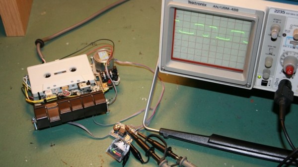
The Datasette device was what allowed interfacing the cassettes to the computer. Tape head alignment was critical to successfully writing and reading data to the cassette. Some models of the Datasette came with a small hole above the keys, to allow access to the adjustment screw of the tape head azimuth position. Tweaking this while looking at a signal meter could help you improve the signal from a bad cassette and prevent load errors. [Jani] tried a commercial solution called “Load-IT” which had a LED bargraph, but it couldn’t help much dealing with tapes with very bad signals. So he built a signal strength meter for his Datasette. He calls it the VU-sette since it uses an analog style meter quite similar to the VU-meters found in many audio equipment.

The hardware is simple and uses commonly available parts. The analog meter is extracted from a Battery Checker sourced from eBay. An op-amp drives the analog meter, and another transistor drives a separate speaker. This can be used to listen in on the cassette, if the speaker is enabled via a push button. [Jani] first breadboarded and tested the circuit before ordering out prototype boards.

To test performance, [Jani] used FinalTAP, a tool for examining, cleaning and restoring digitized data cassette tapes (TAP files) for the Commodore 64 computer. The “LOAD-IT” version worked well with tapes that were in fairly good condition. But his VU-sette version allowed him to adjust the head more precisely and get out a much better read from bad tapes. While on the subject, check out this nice 7-segment bubble LED digital counter for the 1530.

Continue reading “A VU-meter Indicator For A Commodore 1530 Datasette”

High Speed SSD1306 Library

[Lewin] wrote in to tell us about a high speed library for Arduino Due that he helped develop which allows interfacing OLED displays that use the SSD1306 display controller, using DMA routines for faster display refresh time.

Typically, displays such as the Monochrome 1.3″ 128×64 OLED graphic display , are interfaced with an Arduino board via the SPI or I2C bus. The Adafruit_SSD1306 library written by [Limor Fried] makes it simple to use these displays with a variety of Arduinos, using either software or hardware SPI. With standard settings using hardware SPI, calls to display() take about 2ms on the Due.

[Lewin] wanted to make it faster, and the SAM3X8E on the Due seemed like it could deliver. He first did a search to find out if this was already done, but came up blank. He did find [Marek Buriak]’s library for ILI9341-based TFT screens. [Marek] used code from [William Greiman], who developed SD card libraries for the Arduino. [William] had taken advantage of the SAM3X8E’s DMA capabilities to enable faster SD card transfers, and [Marek] then adapted this code to allow faster writes to ILI9341-based screens. All [Lewin] had to do was to find the code that sent a buffer out over SPI using DMA in Marek’s code, and adapt that to the Adafruit library for the SSD1306.

There is a caveat though: using this library will likely cause trouble if you are also using SPI to interface to other hardware, since the regular SPI.h library will no longer work in tandem with [Lewin]’s library. He offers some tips on how to overcome these issues, and would welcome any feedback or testing to help improve the code. The speed improvement is substantial. Up to 4 times quicker using standard SPI clock, or 8 times if you increase SPI clock speed. The code is available on his Github repo.

20 MPH IKEA Poäng Chair With Aerospace-Inspired Control Panel

Spending time at work sitting on the same drab chair can get boring after a while, even if you’re lucky to use a comfortable recliner. If you want to win the Office Olympics, you need something with a bit of pep. [StuffAndyMakes] wanted to build a completely ridiculous motorized office chair. A couple of years in the making, and he’s ready to unleash the 20 MPH IKEA Poäng chair with aerospace-inspired control panel!

The OfficeChairiot MkII, as he has christened it aptly,  is a motorized IKEA Poäng comfy chair. It uses off-the-shelf scooter parts to roll around : Batteries, motors, chains, sprockets, tires, axles, and  bearings. The OfficeChairiot MkII is basically three main parts – the Chassis, the Control Panel and the comfy chair. One of the main parts of the chassis is the motor controller  – The Dimension Engineering Sabertooth 2×60 motor controller – which is also used in beefy battlebots. It’s capable of carrying 1,000 lbs. of cargo and can feed the drive system up to 60 amps per motor channel .

The brain on the chassis is an Arduino Mega which can be controlled via a hand held remote. The Mega also receives data from various sensors for motor temperature, power wire temperature, ambient air temperature, wheel RPM’s, Accelerometer’s, seat occupancy and GPS data. The firmware is designed to ensure safety. The hand held remote needs to ping the on-board Arduino twice a second. If it doesn’t hear from the Remote for whatever reason, the unit stops and turns off the lights.

The Control Panel is one crazy collection of switches, buttons, displays, a missile switch, a master key switch – in all over 30 switches and buttons. All of the devices on the panel are controlled via a second Arduino Mega, helped by a custom multiplexer board to help connect the large number of devices.

Here are a few more features the OfficeChairiot MkII boasts of :

  • 1.5 Horsepower from two 500W scooter motors
  • 20W stereo and MP3 sound effects
  • Weapons sounds, 15 different fart sounds, car alarm, horns, etc.
  • All LED lighting: Headlights, turn signals, 88 undercarriage RGB LEDs
  • Plenty of homemade PCB’s
  • Custom built aluminum body panels (with help from Local Motors, the people behind the 3D printed car)

Aside from the handcrafted wood chassis and circuits boards and firmware, it’s all off-the-shelf stuff. [StuffAndyMakes] plans on open-sourcing the schematics, C++ code and CAD drawings – so post some comments below to motivate him to do so soon. We’d sure like to see a few more of these being built, so that Office Chair racing becomes a competitive sport. Check out the video after the break.

Continue reading “20 MPH IKEA Poäng Chair With Aerospace-Inspired Control Panel”

Training Fish To Feed Themselves

We’ve featured quite a few aquarium and fish feeder hacks on our blog. [RoboPandaPDX] thought of taking it up a notch and make an interactive fish feeder. He built a Fish feeder that train’s them to feed themselves.

A copper bar hangs from the middle of a metal cylinder – much like a bell. The end of the bar has a fish lure. When a fish pushes the lure, the copper bar touches the metal cylinder and  closes the circuit. This signal goes to an Arduino. To catch the attention of the fishes and to “teach” them, an RGB LED is used. The fish need to figure out that the feeder will dispense food only when the LED is ON and the Lure is pushed. If the fish figure that out, and push the lure when the LED is on, a servo is activated which pushes the feeder to deliver 1 unit of fish food. While at it, he added a couple of bells and whistles. A buzzer to indicate when the Lure switch is closed and a 2 line LCD shows how many times the switch has been activated and how long the program has been running.

A Sparkfun  open logger stores the hit count and the minutes and seconds of the hit for data analysis later on. The good news is that it seems to be working. The current code activates the feeder for 30 to 60 minutes every day, which is indicated by the LED. At the end of 9 days,  [RoboPandaPDX] found that the goldfish would hit the Lure when the LED turned on, and then turn around to face where the feeder would dispense food in to the tank. His next plan is to put up some obstacles along the path to see if the fish learn some new tricks. His schematic looks a little iffy (the Lure switch is connected to the RST pin of the Arduino), and it seems he cannot remember why he ever did that. He’s happy that it works though, but we’re sure that’s not the right way to wire it up.

[RoboPandaPDX] is looking for suggestions on improving his interactive feeder, so if you have any, do add them in the comments below.

If you need some more fish feeder ideas, check out this and this that we blogged about earlier.

Resource Monitoring Solution

Electricity, Gas and Water – three resources that are vital in our daily lives. Monitoring them using modern technology helps with conservation, but the real impact comes when we use the available data to reduce wasteful usage over time. [Sébastien] was rather embarrassed when a problem was detected in his boiler only during its annual inspection. Investigations showed that the problem occurred 4 months earlier, resulting in a net loss of more than 450 cubic meters, equivalent to 3750 liters per day (about 25 baths every day!). Being a self professed geek, living in a modern “connected” home, it rankled him to the core. What resulted was S-Energy – an energy resource monitoring solution (translated) that checks on electricity, gas and water consumption using a Raspberry Pi, an Arduino, some other bits of hardware and some smart software.

[Sébastien] wanted a system that would warn of abnormal consumption and encourage his household folks to consume less. His first hurdle was the meters themselves. All three utilities used pretty old technology, and the meters did not have pulse data output that is commonplace in modern metering. He could have replaced the old meters, but that was going to cost him a lot of money. reflective-power-meter-sensor
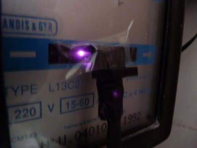
So he figured out a way to extract data from the existing meters. For the Electricity meter, he thought of using current clamps, but punted that idea considering them to be suited more for instantaneous readings and prone for significant drift when measuring cumulative consumption. Eventually, he hit upon a pretty neat hack. He took a slot type opto coupler, cut it in half, and used it as a retro-reflective sensor that detected the black band on the spinning disk of the old electro-mechanical meter. Each turn of the disk corresponds to 4 Watt-hours. A little computation, and he’s able to deduce Watt-hours and Amps used. The sensor is hooked up to an Arduino Pro-mini which then sends the data via a nRF24L01+ module to the main circuit located inside his house. The electronics are housed in a small enclosure, and the opto-sensor looks just taped to the meter. He has a nice tip on aligning the infra-red opto-sensor – use a camera to check it (a phone camera can work well).

Continue reading “Resource Monitoring Solution”

Putting New Into The Old – A Phonograph Upgrade.

[smellsofbikes] recently came into possession of a 1970’s “stereo radio phonograph” cabinet consisting of a vinyl record player, AM and FM radio, and eight track tape player. The radio worked, the turntable didn’t sound too nice, and the tape player didn’t work at all. A new needle fixed the turntable, but the eight-track was in bad shape. So he replaced the tape player with a BeagleBoneBlack which plays streaming internet radio.

Hopefully, this fix is temporary, since he has carefully disconnected the tape player connections in the hope of fixing it soon. The swap out involved a fair bit of engineering, so he’s split his build log into several bite sized chunks. The first step was to set up the BBB, upgrade it and add in all the network and audio related stuff. Audio on the BBB is available only via the HDMI port, but [smellsofbikes] had a USB soundcard handy, so the next step was setting that up. He installed mpg321 – the command line mp3 player and set it up to play music streaming from somafm. Next up was getting some scripts and programs to run automatically during system bootup. The final part of the setup was adding a WiFi router as a repeater connected to the BBB via an ethernet cable. He could have used a tiny WiFi USB dongle, but he already had the router lying around, and he wanted to dedicate USB to audio functions alone, and use the Ethernet port for Internet.

He then worked on identifying the wires that go from the tape player to the amplifier, spliced them, and hooked them up to the audio sound card on the BBB. With this done, the upgrade was more or less complete – the system played streaming music and stations could be switched remotely (via SSH to BBB). [smellsofbikes] reckoned it would be nice to use the existing controls in the phonograph cabinet to control the internet streaming music, instead of controlling it via a remote computer. The cabinet had 4 indicator lamps that indicated which track was being played and a button to switch between tracks. He removed the old indicator panel and put in a fresh PCB, designed in KiCad and cut on his LPKF circuit board plotter. An aluminum knob machined out of hex bar-stock works as the new track change button. At this point, he called it a wrap. The BBB and Asus router go inside the cabinet, and the old (non-functional) tape player is put in place. Quite an interesting build, and we look forward to when he actually gets the tape player working. [Alan Martin], aka “The Most Interesting Engineer In The World” has told him that “it is a moral imperative that you repair the eight-track and get it working”. [Alan] has promised to send [smellsofbikes] a suitcase full of brand new, still in their plastic wrappers, eight-track tapes when he gets it working.

Fail Of The Week : Measuring DC Current Has To Be Easy, Right?

[DainBramage] needed a DC ammeter to check how long his amateur radio station would be able to stay powered on battery backup power. The one’s he already had on hand were a Clamp Meter, which could only measure AC, and another one that measured just a few milliamps. Since he didn’t have one which could measure up to 25A, he decided to build his own DIY DC Ammeter with parts scavenged from his parts bin. Measuring DC current is not too difficult. Pass the current to be measured through a precision resistor, and measure the voltage drop across it using a sensitive voltmeter.

I = V/R

So far, so good. If it’s late at night and you’ve had a lot of coffee, busy building your DC ammeter, things could head south soon. [DainBramage]’s first step was to build a suitable Shunt. He had a lot of old, 1Ω, 10W resistors lying around. He made a series-parallel combination using nine of them to create a hefty 1Ω, 90W shunt (well, 0.999999999 Ohms if you want to be picky). This gave him a nice 1 Volt per Amp ratio, making it easy to do his measurements.

Next step was to hook up the shunt to a suitable voltmeter. Luckily, he had a Micronta voltmeter lying around, ripped out from a Radio Shack product. Since he didn’t have the voltmeter data, he hooked up a 10k resistor across the meter inputs, and slowly increased the voltage applied to the meter. At 260mV, the needle touched full-scale and the voltage across the inputs of the voltmeter was 33mV. [DainBramage] then describes the math he used to calculate the resistors he would need to have a 10A and a 25A measurement range. He misses his chance to catch the fail. His project log then describes some of the boring details of putting all this together inside a case and wrapping it all up.

A while later, his updates crop up. First thing he probably realized was that he needed more accurate readings, so he added connectors to allow attaching a more accurate voltmeter instead of the analog Micronta. At this point, he still didn’t catch the fail although it’s staring him straight in the face.

His head scratching moment comes when he tries to connect his home made ammeter in series with the 12V DC power supply to his amateur radio station. Every time he tries to transmit (which is when the Radio is drawing some current), the Radio shuts off.  If you still haven’t spotted the fail, try figuring out how much voltage gets dropped across the 1Ω shunt resistor when the current is 1A and when it is 5A or more.