A Real Car Remote Controlled With An Arduino… What Could Go Wrong?

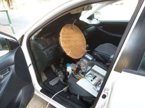
[Gilad] tipped us about his latest project, where he adds plenty of pneumatics and electronics into his wife’s car to remote control it.

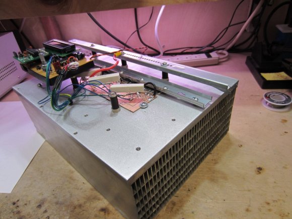
The brake/throttle pedals are actuated by pistons controlled by electronic valves, and a standard DC motor is in charge of turning the wheel. The Arduino code tells us that the valves will be opened as long as the remote up/down channel is above/under given values. The frame is based on Festo aluminium profiles and we’re not sure where the mains used for the DC/DC converters is coming from.  As the valves use 24V and the motor 12V, standard N-Mosfets and power relays are used for voltage conversion. The remote controller [Gilard] used is actually 20 years old, so the output signal of the receiver isn’t actually really clean.

We do hope to never see this car on the road….

Build A Light Following Bristlebot As A Way To Teach Science

light-following-bristlebot

[Ben Finio] designed this project as a way to get kids interested in learning about science and engineering. Is it bad that we just want to build one of our own? It’s a light following bristlebot which in itself is quite simple to build and understand. We think the platform has a lot of potential for leading to other things, like learning about microcontrollers and wireless modules to give it wireless control.

Right now it’s basically two bristlebots combined into one package. The screen capture seen above makes it hard to pick out the two toothbrush heads on either side of a battery pack. The chassis of the build is a blue mini-breadboard. The circuit that makes it follow light is the definition of simple. [Ben] uses two MOSFETs to control two vibration motors mounted on the rear corners of the chassis. The gate of each MOSFET is driven by a voltage divider which includes a photoresistor. When light on one is brighter than the other it causes the bot to turn towards to the brighter sensor. When viewing the project log above make sure to click on the tabs to see all of the available info.

This directional control seems quite good. We’ve also seen other versions which shift the weight of the bot to change direction.

Continue reading “Build A Light Following Bristlebot As A Way To Teach Science”

Brilliant Auto-off Feature For A Bike Light

auto-off-bike-light-switch

If you’re going to use your bicycle as transportation at night you really must have a head and tail light in hopes that the crazy drivers don’t hit you. For good reason, these lights don’t turn themselves off. But [Miceuz] kept forgetting to shut it down upon arrival and always ended up with dead batteries. His quest for an auto-off feature that actually worked ended in a brilliant and simple add-on circuit.

He first thought about using an accelerometer, but couldn’t find one that fit the bill without also adding a microcontroller. He came up with an even simpler circuit, which can be seen at the base of the black plastic housing. It’s a bit of copper clad board with a small spring attached. The spring completes an RC timer circuit which drives a MOSFET. When that circuit is charged, the MOSFET connects power to the bike light. When the cap runs out the MOSFET threshold cuts power and everything turns off. Since the spring jiggles while he rides it provides the momentary connection necessary to charge the capacitor. Stay stationary for about 30 seconds and the auto-off kicks in.

CNC Zen Gardening

The Harford Hackerspace in Baltimore, Maryland just went public with the zen garden they built for the Red Bull Creation contest. It’s a CNC creation that will help ease your frustration with that DIY 3d printer that you just can’t seem to get calibrated correctly.

On the hardware side the base of the machine serves as a sandbox. Finding the correct grain size of the medium was one of the more difficult parts of the build. The stylus is driven along three axes using a gantry common in CNC builds. The pulleys and some brackets were 3d printed, with the remained of the brackets being laser cut from wood. The Bullduino commands the stylus via a stepper motor control board, and drives the LEDs via a bank of MOSFETs. Limiting switches were also included to ensure an error didn’t result in damage to the device.

After the break you can see a build montage put to one of the greatest 8-bit game soundtracks of all time. The one thing we wish they would have shown is the built-in leveling bar that is responsible for “erasing” the garden.

Update: The Harford Hackerspace members came through with a new video that shows the ‘erasing’ process. You’ll find it after the break.

Continue reading “CNC Zen Gardening”

Electric Bike (earplugs Not Included)

It’s obvious this bike has some extra parts. But look closely and you’ll see the chainring has no chain connecting to it. Pedaling will get you nowhere since [PJ Allen] rerouted the chain in order to drive this bicycle using an electric motor.

He’s got beefy motor which pulls 350 Watts at 24 Volts. For speed control he opted to use an Arduino, pumping out PWM signals to some MOSFETs. This results in an incredibly noisy setup, as you can hear in the bench test video after the break. But once this is installed on the bike it doesn’t quiet down at all. You can hear the thing a block away.

The original road test fried the first set of 7A MOSFETs when trying to start the motor from a standstill. It sounds like the 40A replacements he chose did the trick through. We didn’t see any information on the battery life, but if he runs out of juice on the other side of town we bet he’ll be wishing he had left the chain connected to the crankset.

Continue reading “Electric Bike (earplugs Not Included)”

LED Tutorial Demystifies Several Control Techniques

Controlling LEDs is really quite simple. As you know, they need to be current limited which is as easy as applying Ohm’s law to your given set of values. To make things even more even there’s a slew of constant current LED driver chips out there that can be had for a song. But do you have any idea how those constant current circuits work? If not, then [Giorgos Lazaridis’] guide on LED driving and controlling methods will bring you up to speed in no time.

He starts out with the most basic concept, how to light an LED using proper current limiting resistors. But from there he moves on to the juicy bits. He builds a transistor-based constant current driver, then adds voltage regulation for the circuit as seen in the schematic on the left. He moves on to the more robust and efficient method on the right which pairs a MOSFET with that transistor circuit. This is the technique found on each pin of many of those constant current drivers and functions well regardless of the voltage input level.

He’s been producing videos to go along with these articles. After the break you can watch the episode that accompanies the schematic on the left. Continue reading “LED Tutorial Demystifies Several Control Techniques”

DIY Quadcopter For Around $200

We think [FlorianH] did a bang-up job of prototyping his Minima Quadcopter on the cheap. The total bill comes in right around $200 and we’re very happy with the quality of parts as well as the results.

Here you can see the top of the double-sided board which he etched to host all of the components. At each corner there is a power MOSFET which drives the motor. At first glance we thought that the Xbee module was acting as the radio control and processer as well. But on the underside you’ll find an ATmega32 which is responsible for reading the Gyroscope sensor and Accelerometer, processing these signals and driving each MOSFET via PWM lines to provide stability.

You can see some flight tests after the break. [FlorianH] mentions that there is some oscillation in the feedback loop when both the gyro and accelerometer are used. But cut the accelerometer out of the equation and the platform is rock-solid.

This build uses carbon tubes to mount the motors, which we think will be a little more robust than the all-PCB designs are.

Continue reading “DIY Quadcopter For Around $200”