Magnetic Circuits Are More Attractive Than Breadboarding

Let’s face it, breadboarding can be frustrating, even for advanced electronics wizards. If you have an older board, you could be dealing with loose tie points left from large component legs, and power rails of questionable continuity. Conversely, it can be hard to jam just-made jumper wires into new boards without crumpling the copper. And no matter what the condition of the board is, once you’ve plugged in more than a few components, the circuit becomes hard to follow, much less troubleshoot when things go pear-shaped.

In the last twenty years or so, we’ve seen systems like Snap Circuits and Little Bits emerge that simplify the circuit building process by making the connections more intuitive and LEGO-like than even those 160-in-1 kits where you shove component legs between the coils of tight little springs. You will pay handsomely for this connective convenience. But why should you? Just make your own circuit blocks with cardboard, magnets, and copper tape. It should only cost about 10¢ each, as long as you source your magnets cheaply.

[rgco] gives the lowdown on building a minimal set of 23 component and connector blocks using 100 magnets. He’s got 11 example circuits to get you started, and some example videos of more advanced circuits that got tacked up after the break.

This method of making the circuit look more like the schematic may be the best way for the visually-inclined to learn electronics. But the best way to learn electronics depends on where you’re coming from.

Continue reading “Magnetic Circuits Are More Attractive Than Breadboarding”

Over-Engineered Mailbox Flag Machined Using Under-Engineered Mini-Lathe

[Tim Nummy] used his cheap, Chinese, bench mini-lathe to make a non-terrible mailbox flag holder (YouTube video, embedded below). Tim posts videos on his channel about garage hobby projects, many of which are built using his mini-lathe, often based on suggestions from his followers. One such suggestion was to do something about his terrible mailbox flag – we’re guessing he receives a lot of old-school fan mail.

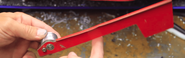
He starts off by planning the build around 1 ¼ inch aluminum bar stock, a 688 bearing, three neodymium magnets and some screws. The rest of it is a “think and plan as you go along” project, but essentially, the new holder is in three pieces. An inner piece goes inside the mail box and holds the assembly to the mail box. The middle piece holds the two magnets which act as end-stops or limits for the flags raised and lowered positions. The final, outer piece holds the flag itself, and the bearing which allows it to rotate freely.

This part also has the third magnet embedded in it to work with the other two magnets for the limits. The use of magnets is cool, but a ball catch with two detents would have worked just as well. It’s a great simple project to follow for those who want to wet their feet on lathe work. [Tim] has also posted links to all of the tools and equipment seen in the video, so check that out if anything catches your fancy.

But workshop veterans will almost certainly cringe at several places along the video. The main one that caught our eye is obviously the shaky lathe itself. It could do with a heavier workbench, proper leveling, foundation bolts or anti-vibration mounts. And from the looks of it, the tail stock isn’t any rock steady too. Although the lathe is variable speed, the chuck rpm is set too high for aluminum, and the lack of cutting fluid makes it even more troublesome. Using oil, or even some cutting fluid, while tapping would have been wise too.

We’re not sure if it’s the shaky foundation or poor feed control, but the step cut for mounting the bearing is over-sized by a whole lot more and requires a big goop of retaining compound to glue the bearing in place. But the end result works quite well, including the magnetic catches – a complex solution for a simple problem.

We’re sure our keen-eyed readers will likely spot some more issues in [Tim]’s methods, so go at it in the comments below, but please make sure to rein in the snark and keep your feedback positive.

Continue reading “Over-Engineered Mailbox Flag Machined Using Under-Engineered Mini-Lathe”

Digital Opponent In An Analog Package

Unsatisfied with the present options for chess computers and preferring the feel of a real board and pieces, [Max Dobres] decided that his best option would be to build his own.

Light and dark wood veneer on 8mm MDF board created a board that was thin enough for adding LEDs to display moves and for the 10mm x 1mm neodymium magnets in the pieces to trip the reed switches under each space. The LEDs were wired in a matrix and connected to an Arduino Uno by a MAX7219 LED driver, while the reed switches were connected via a Centipede card. [Dobres] notes that you’ll want to test that the reed switches are positioned correctly — otherwise they might not detect the pieces!

Continue reading “Digital Opponent In An Analog Package”

Speaker Science Project

They probably won’t please the audiophiles, but [KJMagnetics] shows you that can create a pair of speakers with some magnets, some plastic cups, and a bit of magnet wire. Creating speakers out of junk isn’t a new idea, of course. However, there’s something pleasant about the build. Maybe it is the symmetry of the cups or the workbench look of the woodworking.

We couldn’t help but think that this would make a good science fair project or a classroom activity. Especially since there is a good write up on how speakers work and it would be easy to make simple changes to test different hypothesis about speakers. For example, what happens with more or less wire in the coils? What magnets work best? What does best even mean? Is it louder? Less distortion?

Continue reading “Speaker Science Project”

Dirt Cheap Motor Balancing And Vibration Analysis

Ever the enterprising hacker and discerning tool aficionado, [Chris] knows the importance of “feel”. As a general rule, cheap tools will shake in your hand because the motors are not well-balanced. He wanted a way to quantify said feel on the cheap, and made a video describing how he was able to determine the damping of a drill using a few items most people have lying around: an earbud, a neodymium magnet, scrap steel, and Audacity.

He’s affixed the body of the drill to a cantilevered piece of scrap steel secured in a vise. The neodymium magnet stuck to the steel interrupts the magnetic field in the earbud, which is held in place with a third hand tool. [Chris] taped the drill’s trigger down and controls its speed a variac. First, [Chris] finds the natural frequency of the system using Audacity’s plot spectrum, and then gets the drill to run at the same speed to induce wobbling at different nodes. As he explains, one need not even use software to show the vibration nodes—a laser attached to the system and aimed at a phosphorescent target will plot the sine wave.

Just for fun, he severely unbalances the drill to find the frequencies at which the system will shake itself apart. Check it out after the break.

Continue reading “Dirt Cheap Motor Balancing And Vibration Analysis”