Spectrum Analyzer On The Cheap

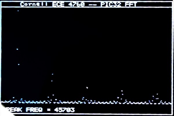
Provided you have an NTSC-compatible TV you can build yourself a really inexpensive spectrum analyzer. From there you just need one trivial piece of hardware to complete this build. [Bruce Land] has come up with a spectrum analyzer that shouldn’t cost any more than $5, if that’s what’s been keeping you from adding this tool to your workbench!

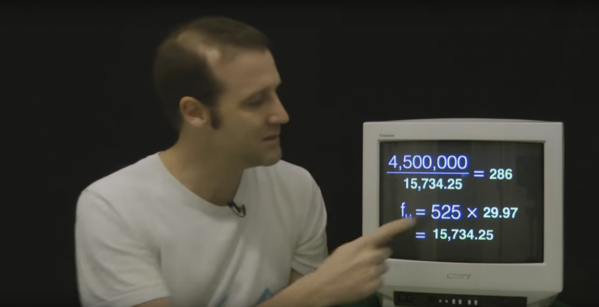
The spectrum analyzer is based on a PIC32 microcontroller which was previously proven in his Oscilloscope project. [Bruce] has managed to squeeze quite a bit out of this robust chip; the spectrum analyzer has 450 kHz bandwidth and runs a 256 Hz TV display and can output over 30 updates per second. The microcontroller runs the Fast Fourier Transform (FFT) to do calculations, with great results.

[Bruce] notes that the project was based on TV framework from another project, and that the FFT was added on top of that. Be sure to check out the source code on the project site if you’ve been on the hunt for an inexpensive spectrum analyzer, and if you need something with more processing power but only slightly more money, check out the FFT that runs on the Raspberry Pi’s GPU.

ATtiny85 Does Over The Air NTSC

[CNLohr] has made a habit of using ATtiny microcontrollers for everything, and one of his most popular projects is using an ATTiny85 to generate NTSC video. With a $2 microcontroller and eight pins, [CNLohr] can put text and simple graphics on any TV. He’s back at it again, only this time the microcontroller isn’t plugged into the TV.

The ATtiny in this project is overclocked to 30MHz or so using the on-chip PLL. That, plus a few wires of sufficient length means this chip can generate and broadcast NTSC video.

[CNLohr] mentions that it should be possible to use this board to transmit closed captioning directly to a TV. If you’re looking for the simplest way to display text on a monitor with an AVR, there ‘ya go: a microcontroller and two wires. He’s unable to actually test this, as he lost the remote for his tiny TV from the turn of the millennium. Because there’s no way for [CNLohr] to enable closed captioning on his TV, he can’t build the obvious application for this circuit – a closed caption Twitter bot. That doesn’t mean you can’t.

Video below.

Continue reading “ATtiny85 Does Over The Air NTSC”

Video Voice Visualization

For their ECE 4760 final project at Cornell, [Varun, Hyun, and Madhuri] created a real-time sound spectrogram that visually outputs audio frequencies such as voice patterns and bird songs in gray-scale video to any NTSC television with no noticeable delay.

The system can take input from either the on-board microphone element or the 3.5mm audio jack. One ATMega1284 microcontroller is used for the audio processing and FFT stage, while a second ‘1284 converts the signal to video for NTSC output. The mic and line audio inputs are amplified individually with LM358 op-amps. Since the audio is sampled at 8KHz, a low-pass filter gets rid of frequencies above 4KHz.

After the break, you can see the team demonstrate their project by speaking and whistling bird calls into the microphone as well as feeding recorded bird calls through the line input. They built three controls into the project to freeze the video, slow it down by a factor of two, and convert between linear and logarithmic scales. There are also short clips of the recorded bird call visualization and an old-timey dial-up modem.

Continue reading “Video Voice Visualization”

The guts of a Z80 MicroTV Clock

A Z80 Micro TV Clock

As an adventure in computer history, [Len] built up a clock. The Z80 Micro TV Clock brings together a homebrew computer and three Micro TVs into a rather large timepiece.

The computer powering the clock runs the CP/M operating system. This OS was eventually released as open source software, and a variety of homebrew computer projects have implemented it. This clock is based on an existing breadboard CP/M machine, which includes schematics and software.

With an OS running, [Len] got a text editor and C compiler working. Now custom software could be written for the device. Software was written to interact with a Maxim DS12885 Real Time Clock, which keeps the time, and to output the time to the display controllers.

The Micro TVs in this build are Sony Watchman displays featuring a 2″ CRT. The devices had no video input port, so [Len] ripped them open and started poking around. The NTSC signal was found by probing the board and looking for the right waveform.

To drive the TVs from CP/M, a custom video driver was built. This uses three relatively modern ATmega328P microcontrollers and the arduino-tvout library. All of these components are brought together on a stand made from wood and copper tubing, making it a functional as a desk top clock

THP Entry: A CPLD Video Card With VGA And NTSC

NTSC

[PK] is working on a very simple video card, meant to output 640×480 VGA with a cheap CPLD. The interface will be 5 Volt SPI, meaning there’s a ton of potential here for anyone wanting put a reasonable (and cheap) display in a microcontroller project. The project has come a long way, and his latest update showcases something that has only been done once before: color NTSC with programmable logic

The brains of the outfit is a $5, 100-pin CPLD from Xilinx. Apart from that, the rest of the components are a crystal, PLL, and an almost hilarious number of resistors for the R2R ladder. The one especially unique component is the 25.056815 MHz crystal – multiply by that by two, and it’s fast enough to drive a VGA monitor. Divide the crystal by seven, it’s the 3.579545 MHz you need for an NTSC colorburst frequency. That’s VGA and NTSC in a single programmable logic project, something the one FPGA project we could find that did color NTSC couldn’t manage.

The next step in the project is designing a PCB and figuring out the code for the framebuffer. [PK] put up a demo showing off both VGA and NTSC; you can check that out below.


SpaceWrencherThe project featured in this post is an entry in The Hackaday Prize. Build something awesome and win a trip to space or hundreds of other prizes.

Continue reading “THP Entry: A CPLD Video Card With VGA And NTSC”

Demystifying NTSC Color And Progressive Scan

NTSC

Black and white NTSC is simple – it can, and was, done with vacuum tubes for a long, long time. Color is just weird, though. It runs at 29.976 frames per second, uses different phases of the carrier for different colors, and generally takes a while to wrap your head around. [Sagar] is doing a series on the intricacies of NTSC, and the latest post deals with color and progressive scanning versus interlacing, or as it is better known, how classic game consoles and home computers generate video.

The test bed for [Sagar]’s video experimentations is a circuit containing an ATMega16, a 4-bit shift register, and a 14.31818 MHz clock. This clock is much faster than the 3.579545 MHz clock in an NTSC carrier frequency – exactly four times as fast – allowing the shift register to output four different phases of the carrier frequency a 0°, 90°. 180°, and 270°. Playing with some of the pins on the ATMega in the circuit results in a palette being generated on any old TV.

NTSC requires interlaced scanning, or sending an entire screen of even lines, then an entire screen of odd lines, at around 60 fields per second. The Nintendos and Segas of yesteryear didn’t bother with this, instead opting to send half the vertical resolution at double the frame rate. This is known as a progressive scan. [Sagar] found that this resulted in some image artifacts when displayed on a modern LCD, and moving back to an interlaced mode fixed the problem. All the code and files are up on the gits. If you’re feeling adventurous, this is exactly how projects like the Uzebox have created homebrew game consoles using little more than the ATMega found in [Sagar]’s build.

A Video Vectorscope Oscilloclock

Tek 520A Oscilloclock

Back in the days of analog TV, vectorscopes were used to view video signals. [Aaron] has taken an old Tek 520A NTSC vectorscope and converted it into his newest oscilloclock.

The scope was originally designed to look at the signal provided by composite video. It draws vectors on a polar plot. By using test patterns such as color bars, you can ensure equipment is creating the correct color output. These scopes were so commonly used that many digital systems still provide a simulated vectorscope for color analysis. Vectorscopes were designed to be left on constantly, which is a good quality for a clock.

[Aaron] has a history of converting oscilloscopes into clocks, which we have featured in the past. This build is similar, using his custom control hardware to drive the display. Since analog vectorscopes are pretty much obsolete, you can find them on eBay at low prices, so these oscilloclocks could be relatively cheap to build.

In the write up, you get a teardown of the Tek 520A, showing the modifications made to build the clock. After the break, check out a video of the Tek 520A Oscilloclock.

Continue reading “A Video Vectorscope Oscilloclock”