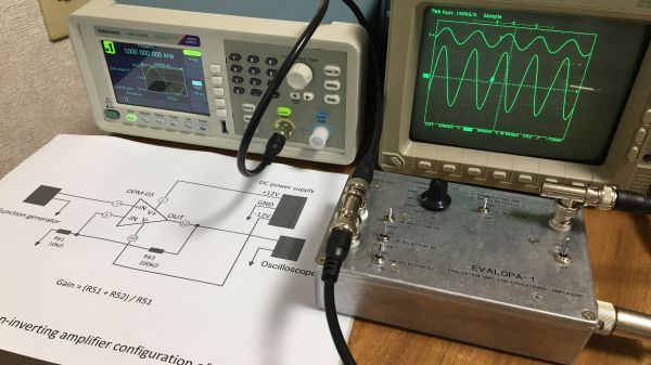
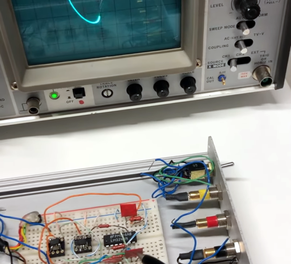
Op-Amp Challenge: Compare Op-Amps, By Listening To Them

In the world of audiophilia there are arguments that rage over the relative merits of particular components. Sometimes this can reach silly levels as in the high-end ALPS pot we once saw chosen as a volume control whose only task was to be a DC voltage divider feeding a pin on a DSP, but there are moments where such comparisons might have a bit of merit. To allow the comparison of different op-amps in a headphone amplifier, [Stephan Martin] has created a stereo amplifier board complete with sockets to take single or dual op-amp chips.

The circuit is based upon a design from the 1990s which as far as we can see is a pretty conventional non-inverting amplifier. It has an on-board op-amp to create a virtual ground, and three sockets for either two single or one dual op-amp to create a stereo headphone amplifier.

So the burning question is this: will you notice a difference? We’re guessing that assuming the op-amps under test are to a sufficient specification with a high enough impedance input and enough output current capability, the differences might be somewhat imperceptible without an audio analyser or the hearing of a ten-year-old child.

Need more of an audio fix? Try our Know Audio series.


Op-Amp Challenge: A Low Noise Amplifier For Those Truly Low Noise Measurements

When something is described as “Low Noise”, it is by the nature of the language a relative phrase. The higest quality magnetic tape is low noise compared to its cheaper sibling for example, but still has noise many would consider unacceptable. In instrumentation however, “Low Noise” has to really mean just that, with a range of specialist techniques to produce circuitry with a truly low noise level for the most demanding of signal applications. As an example [Floydfish] has created a low noise instrumentation amplifier that should serve as a learning exercise for anyone interested in pushing low noise circuitry to the limit.

Anyone who can dredge the hazy recesses of their mind for barely-remembered electronics lectures will know that the overall noise figure of a system is dictated by that of its first component. Thus perhaps the most interesting part of the schematic is at the input, where a row of low-noise op-amps are presented in parallel. We have to admit having to look this one up, to find that it’s a technique whereby the signal outputs of each chip are the same and thus sum, while the noise output of each is different and thus the summed noise output is proportionally lower. This stage is then followed by a buffer and a set of filters for different output frequency ranges.

Our op-amp competition of which this is a part is certainly delivering the goods when it comes to the amny techniques with which these versatile parts can be used. Few of us may need to make such a low noise amplifier, but at least now we’ve learned how.

Op-Amp Challenge: Get More From A Single Wire With An Analogue Adder

It’s been a running battle in some quarters for years, whether analog sensor processing is better than digital. Proponents of digital are sometimes driven by lack of familiarity with analog circuitry, while analog die-hards point to delays and software crashes in microcontrollers. We’d probably toe the line that a mixture of the two skills is best, but [paul] has gone full-on for the analog side with his position and limit sensor for a remote telescope. The ‘scope had only one control wire carrying a digital signal, so how was he to get extra information down it? The solution was to overlay a DC voltage, and use a summing network composed of a series of op-amps to encode position and limit data as voltage.

In operation, the circuit is a straightforward DC summing amplifier of the type that op-amps were designed for and at which they excel. We’re not so sure it needs the high-precision resistors and the choice of op-amps seems the wrong way round with the AD8532’s high current output being better suited to driving the line than straightforward summing, but we can see it does the job. If you’re after a demonstration of a DC summing amplifier using an op-amp, here’s your project. Meanwhile if you’re curious about an op-amp inside the black box, take a look at one of the simplest integrated circuit op-amps ever made.

Op-Amp Challenge: Reliable Peak Power Measurement

As part of our Op-Amp Challenge we’re seeing a wide diversity of entries showcasing the seemingly endless capabilities of these extremely versatile parts. Another one comes from [Joseph Thomas], who when faced with the need to measure the properties of an automotive spark plug, came up with a precision peak detector to hold on to the energy level used when firing it.

It starts with an op-amp buffer feeding a diode and capacitor. The capacitor is charged through the diode and holds the level, which can be read through another op-amp. Finally there’s an opto-isolated transistor to discharge the capacitor before a fresh reading is taken.

It’s a simple enough circuit but a very effective one. The op-amps used are bit old-school FET devices, but aside from the high impedance input their performance is hardly critical. Yet another op-amp circuit to hold in reserve should you ever need to perform this task.

Op Amp Challenge: An Ultra-Cheap PH Sensor Amplifier

It’s rare in 2023 for an instrument to be entirely analog, instead it’s more normal for a front-end to feed the analog-to-digital converter (ADC) in a microcontroller. Typically the front-end will do the job of transforming whatever the output range of the sensor is, and present it to the microcontroller in whatever range it accepts. [David] had exactly this problem with a pH sensor, and rather than buy an expensive module to do the job he designed his own.

The sensor in question produces a relatively tiny voltage of -0.414 to +0.414 volts, and requires a very high input impedance. A FET input op-amp is selected, with the ground of the sensor shifted upwards into the positive range by a voltage divider. This then feeds a second op-amp that amplifies the resulting DC voltage for the microcontroller input.

This circuit is an especially simple op-amp application, and is a typical one for a sensor interface where a DC voltage needs to be brought into range of a microcontroller. If you’re not used to op-amp circuits then take a look, this type of analogue circuit is not difficult and might just save your butt some time.

Want to know more about simple op-amp circuits? Have we got the video for you!

Op Amp Challenge: An Op-Amp Buck Regulator

Switching regulators have delivered such convenience and efficiency compared to their linear siblings, that it’s now becoming rare to see an old-style three-terminal regulator. Modern designs have integrated to such an extent that for many of us the inner workings remain something of a mystery. It’s still possible to make switching regulators from first principles though, which is what [Aaron Lager] has done by designing a buck regulator from a quad op-amp IC,

It’s an entry in our Op Amp Challenge and it appears to be a work in progress, but the design is solid enough. We’re no fans of the schematic style of representing an op-amp chip as a rectangle rather than individual op-amps, but it’s simply a PWM generator with a final op-amp used as a driver for the usual diode-inductor-capacitor network. We’re guessing that the op-amp driver won’t make this the most powerful of switchers, but in this case that’s hardly the point. Build this if you’re interested in taking an op-amp out of its normal sphere, or if you’re interested in the workings of a buck converter.

Need more in the way of switching regulators from first principles? We’ve got you covered, with the ultimate regulator kit of parts, the Fairchild UA723.

Op Amp Challenge: What’s Your Monitor’s Delay?

In the days of CRT displays, the precise synchronization between source and display meant that the time between a video line appearing at the input and the dot writing it to the screen was constant, and very small. Today’s display technologies deliver unimaginable resolutions compared to the TV your family had in the 1970s, but they do so at the expense of all their signal processing imposing a much longer delay before a frame is displayed. This can become an issue for gamers, but also with normal viewing, because in some circumstances the delay can be long enough for it to be audible in a disconnect between film and soundtrack. It’s something [Mike Kibbel] has addressed with his video input delay meter, and it makes for a very interesting project.

At its heart is an FPGA, and in the video below the break he goes into great detail about its programming. It both generates a DVI output to drive the monitor and performs the measurement. The analog to digital converter side of the circuit is interesting, he has a photodiode and an op-amp driving a comparator to form a simple 1-bit converter. He takes us through the design process in detail, with such useful little gems as the small amount of hysteresis applied to the comparator.

There are probably many ways this project could have been implemented, but this one is both technically elegant and extremely well documented. Definitely worth a look!

Continue reading “Op Amp Challenge: What’s Your Monitor’s Delay?”