There’s a lot of data on magnetic media that will soon be lost forever, as floppies weren’t really made to sit in attics and basements for decades and still work. [Chris Evans] and [Phil Pemberton] needed to read some disks that reportedly contained source code for several BBC Micro games, including Repton 3. They turned to Greaseweazle, an interface board that can dump just about any kind of floppy disk if it is attached to the right drive. The problem is that Greaseweazle couldn’t read the disks due to CRC errors. Time to break out the oscilloscope and read the disk manually, which is what they did.
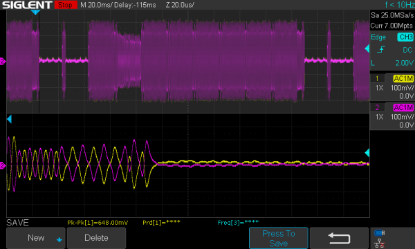
Greaseweazle provides a nice display of read sectors and shows timing coming from the floppy read head. The disk in question looked good with reasonably clean timing clocks except in the area of one sector. At that point, the clocks degenerated into noise. Looking on the disk, it was easy to see why. The actual media had a small dent in it.
A bench oscilloscope is one of the most invaluable tools in the hardware hacker’s arsenal, but even the slimmest digital models are a bit large to be part of your everyday electronic carry. Sure you could throw one of those cheap pocket scopes in your bag, but what if there was an even easier way to take a peek at a few signals while you’re on the go?
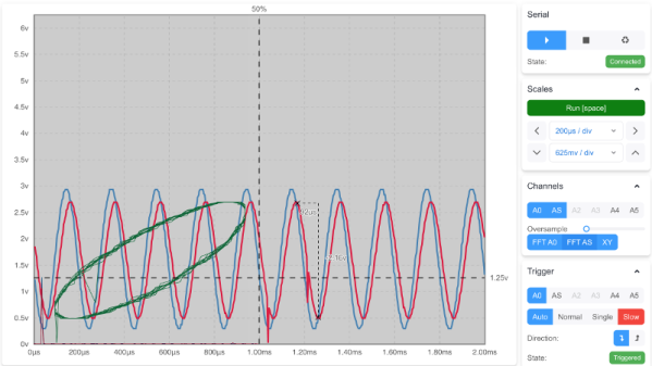
For those who roam, the Arduino-web-oscilloscope project created by [David Buezas] is worth a close look. Using the Web Serial API built into recent versions of Google’s Chrome browser, this project allows you to pop open a software oscilloscope without installing anything locally. Whether it’s a public computer or that cheap Chromebook you keep around for emergencies, a valuable tool is just a few clicks away.
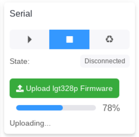
Flashing the MCU from the web interface.
Of course, there has to be some hardware involved. Despite what you might think given the name of the project, the code currently only supports the Logic Green LGT8F328P microcontroller. This cheap ATmega328P clone not only runs at 32 Mhz but according to [David], many operations can be done in fewer clock cycles than on the original 328P. In short it’s fast, and fast is good if you want more samples.
One of the best parts about this project is that a function to flash the firmware to the LGT8F328P is built right in the web interface. With the oscilloscope running in the browser, you just need to plug in a blank board, click the button to flash it, and start taking measurements. You could outfit a whole classroom or hackerspace with basic oscilloscopes in minutes, with a per-seat cost of just a few bucks.
Now as you might expect, there are some pretty hard limits on what you can realistically measure with this setup. For one thing, the board can’t handle anything higher than 5 volts. Even the cheapest oscilloscope kit is still going to be an upgrade, but the fact you can spin this up almost anywhere for the cost of a cheap MCU board makes it hard to complain about the results.
For hackers on a tight budget or with limited bench space, a USB oscilloscope can be a compelling alternative to a dedicated piece of hardware. For plenty of hobbyists, it’s a perfectly valid option. But while the larger discussion about the pros and cons of these devices is better left for another day, there’s one thing you’ll definitely miss when the interface for your scope is a piece of software: the feel of physical buttons and knobs.
But what if it doesn’t have to be that way? The ScopeKeypad by [Paul Withers] looks to recreate the feel of a nice bench oscilloscope when using a virtual interface. Is such a device actually necessary? No, of course not. Although one could argue that there’s a certain advantage to the feedback you get when spinning through the detents on a rotary encoder versus dragging a slider on the screen. Think of it like a button box for a flight simulator: sure you can fly the plane with just the keyboard and mouse, but you’re going to have a better time with a more elaborate interface.
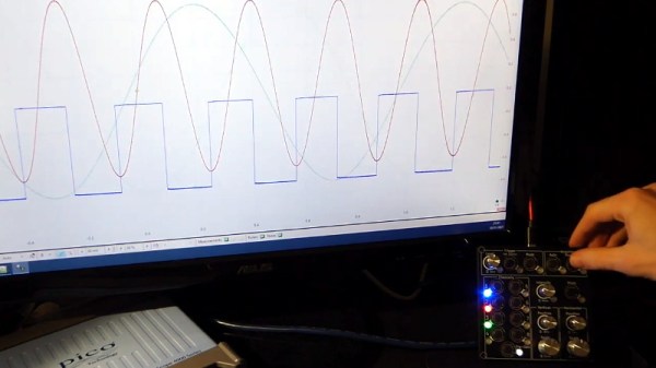
The comparison with a flight simulator panel actually goes a bit deeper, since that’s essentially what the ScopeKeypad is. With an STM32 “Blue Pill” microcontroller doing its best impression of a USB Human Interface Device, the panel bangs out the prescribed virtual key presses when the appropriate encoder is spun or button pressed. The project is designed with PicoScope in mind, and even includes a handy key map file you can load right into the program, but it can certainly be used with other software packages. Should you feel so inclined, it could even double as a controller for your virtual spaceship in Kerbal Space Program.
We know what you’re thinking. It’s a bad power supply, of course it was capacitors to blame. But even if we all intuitively know at this point that bad caps are almost always the culprit when a PSU gives up the ghost, it’s not always easy to figure out which one is to blame. Which is why this deep dive into a failed ETK450AWT by [eigma] is worth a look.
The first sign of trouble was when the computer would unexpectedly reboot with nothing in the system logs to indicate a problem. Eventually, [eigma] noticed a restart before the operating system even loaded, which confirmed the hardware was to blame. A quick look at the PSU output with a voltmeter showed things weren’t too far out of spec, but putting an oscilloscope on the 12 V line uncovered a nasty waveform that demanded further investigation.
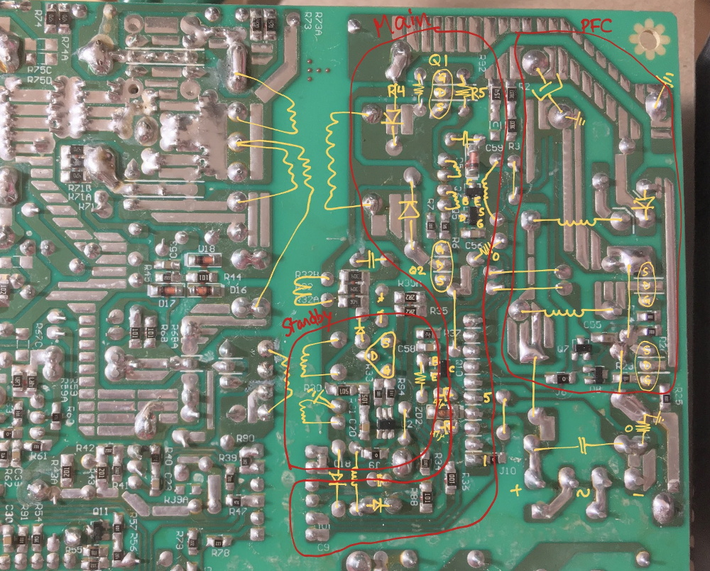
Connecting all the dots.
By carefully following traces and comparing with common PSU diagrams, [eigma] was able to identify the SG5616 IC that checks the various voltages being produced by the PSU and generates the PWR_OK signal which tells the motherboard that everything is working normally. As before, all of the DC voltages at this chip seemed reasonable enough, but the pin that was measuring AC voltage from the transformer was showing the same ripple visible on the 12 VDC line.
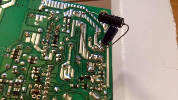
Even more digging uncovered that the transformer itself had a control IC nestled away. The 13 VDC required by this chip to operate is pulled off the standby transformer by way of a Zener diode and a couple capacitors, but as [eigma] soon found, the circuit was producing another nasty ripple. Throwing a few new capacitors into the mix smoothed things out and got the PSU to kick on, but that’s not quite the end of the story.
Pulling the capacitors from the board and checking their values with the meter, [eigma] found they too appeared to be within reasonable enough limits. They even looked in good shape physically. But with the help of a signal generator, he was able to determine their equivalent series resistance (ESR) was way too high. Case closed.
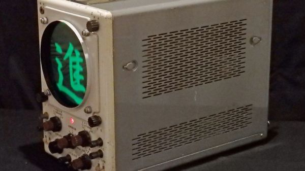
Nostalgia aside, there are a few things an analog scope can still do better than a digital, with oscilloscope art being a prime example. The blue-green glow of phosphors in a real CRT just add something special to such builds, and as a practitioner of this craft, [Aaron] decided to paint a New Year’s affirmation on his oscilloscope screen, in Japanese calligraphy of all things.
When used in X-Y mode, analog oscilloscopes lend themselves nicely to vector-based graphics, which is the approach [Aaron] has taken with previous “Oscilloclock” builds, like the Metropolis Clock. The current work, however, doesn’t use vector graphics, opting instead to turn the scope into the business end of a VGA display. He had previously developed the hardware needed to convert a VGA signal into X- and Y-axis analog outputs, so the bulk of the work was rendering the calligraphy, first in ink and then scanning and processing the results into a file. In keeping with the Japanese theme, [Aaron] chose a rare scope from Nihon Tsushinki Co., Ltd., from 1963. It’s a beautiful piece of equipment and obviously lovingly restored, and with the VGA adapter temporarily connected, the four Japanese characters scroll gracefully up the screen, delivering the uplifting message: “Steady progress, day by day.”
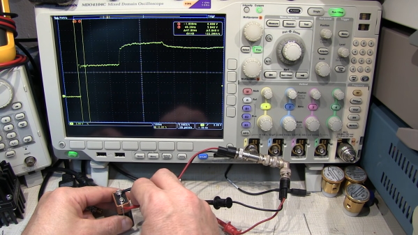
“Time-domain reflectometry” sure sounds like something that needs racks of expensive equipment to accomplish. In reality, TDR is just measuring the time between injecting a pulse into a cable and receiving its echo, either from the other end of the cable or from some fault or defect along the way. It’s a useful technique, and as [Allen Wolke (W2AEW)] shows us, it can be accomplished with little more than a battery, a resistor, and an oscilloscope. And a little math, of course.
There are, of course, dedicated time-domain reflectometers, but all of them are really just elaborations of the basic principles [W2AEW] demonstrates with his simple setup. The oscilloscope is set up with a tee connector on one channel; one side of the tee is connected to the cable under test, while the shield conductor of the other side is connected to the negative terminal of a 9V battery. A resistor connected to the center conductor is used to complete the circuit, which sends a brief pulse down the test cable. The scope is set up to capture the outgoing pulse as well as the return pulse, allowing the time between the two to be measured. Some simple math gives the length of the cable, the distance to a fault, or with a little rearrangement, the velocity factor of the cable.
The video below shows the simple method at work on coax and Cat 5e Ethernet cable. It even worked on a roll of zip cable, which was a little surprising. If this technique is too simple, you can always elaborate a bit and roll your own TDR tester. Googly eyes optional, of course, but recommended.
There aren’t many brands that inspire the kind of passion and fervency among its customers as Tektronix does. The venerable Oregon-based manufacturer of top-end test equipment has produced more collectible gear over the last 75 years than just about anyone else.
Over that time they have had plenty of innovations, and in the 1970s they started looking into miniaturizing their flagship oscilloscopes. The vintageTEK museum, run by current and former employees, has a review of the design process of the 200 series of portable oscilloscopes that’s really interesting. At a time when scopes were portable in the way a packed suitcase is portable, making a useful instrument in a pocketable form factor was quite a challenge — even for big pockets.
The article goes into great detail on the back-and-forth between the industrial designers, with their endless stream of models, and the engineers who would actually have to stuff a working scope into whatever case they came up with. The models from the museum’s collection are wonderful bits of history and show where the industrial designers really pushed for some innovative designs.
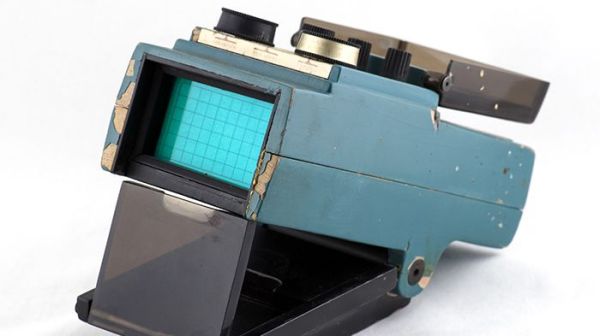
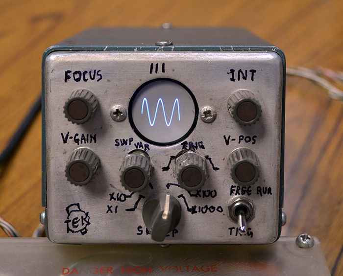
Some of the models are clearly derived from the design of the big bench scopes, but some have innovative flip-down covers and other interesting elements that never made it to production. Most of the models are cardboard, but some were made of aluminum in the machine shop and sport the familiar “Tek blue” livery. But the pièce de résistance of the collection is a working engineering model of what would become the 200-series of miniscopes, a handmade prototype with a tiny round CRT and crudely labeled controls.
The vintageTEK museum sounds like another bucket-list stop for computer and technology history buffs. Tek has been doing things their own way for a long time, and stopping by the museum is sure to be a treat.