Here’s a step-by-step guide for printing etch resist directly to copper clad boards. Two methods of making printed circuit boards at home have long dominated as the favorites; using photo-resist, and the toner-transfer method. The latter involves printing board artwork on a laser printer and then ironing it onto the copper clad. We’ve seen some efforts to print toner directly to the copper, or to use ink to adhere toner and then heat fuse it, but this hack is the first one we remember seeing that uses an inkjet printer directly.
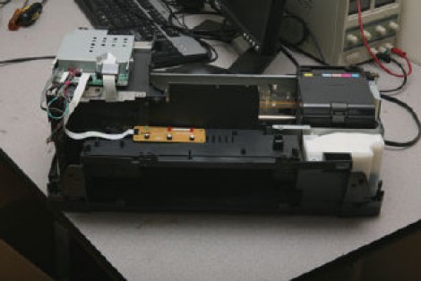
The best reason inkjet printing isn’t often used is do to the ink’s iability to protect copper from the etchant. This method uses MISPRO ink that is pigment based and will resist the acid. An Epson Stylus Photo R260 printer was chosen because you can get refillable printer cartridges which work with the ink, and they’re fairly easy to modify. In order to feed substrate through the device it needs some physical alteration to make room for the thickness of the material, and an ATtiny13 has been added to trick one of the sensors.
Unfortunately we didn’t find photos of the printed resist. But there is source code available for the tiny13 if you do give this a try.
[Thanks Pavlejo]