AVR DDS Signal Generator Improvements

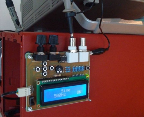
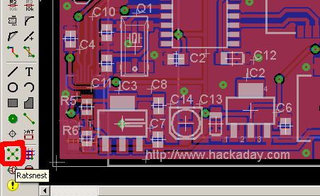
[Vassilis Papanikolaou] took a good thing and made it better with some design upgrades to this AVR based signal generator. We looked at version 1.0 of this tool back in 2006 and since then it saw an upgrade to 2.0. But [Vassilis] wanted to take things one step further, with a compact single-sided PCB. What you see above is the beautiful result of his work; a professionally made board that is compact, uses through-hole components, and has zero wire jumpers.

If you want to build one for yourself there’s a great parts list as well as board artwork and schematic. The system uses an ATmega16 so you’ll need a way to program one. There’s also just a bit of firmware tweaking to remap the control buttons to match the updated hardware layout.

Building A UV Exposure Box

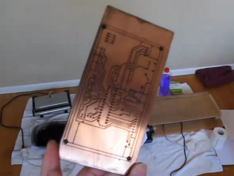
There are two methods of using etchant resist when making circuit boards. We use the toner transfer method that requires ironing on laser toner to the copper, but you can also use chemical resist that reacts to ultraviolet light. [Bogdan] decided to start doing more of the latter so he built a UV exposure box to make the process easier.

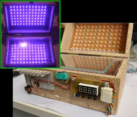
It is possible to use flourescent light bulbs for this, but he decided to use UV LEDs, a method we’ve also seen before. But there’s always room to innovate, and [Bogdan] built-in a couple of nice features that are new to us. Because the UV light can be bad for your eyes, he included a set of red visible-light LEDs on the bottom half of the box that are used to align two layers of exposure mask when making double-sided boards. There’s also a switch that automatically shuts off the UV light when the box is opened. And as the coup-de-grace, he added a programmable timer to regulate the exposure, using his newly created box when etching the PCB for it.

Vapor Phase Reflow Soldering

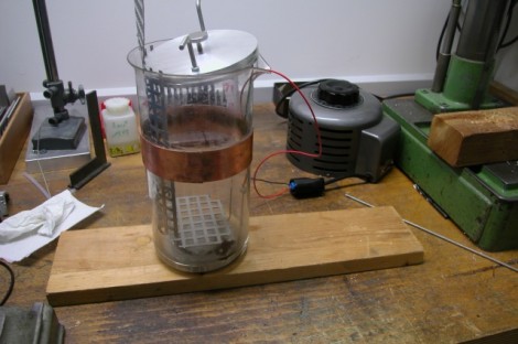
Ditch that old toaster oven and move to the next level of surface mount soldering with this vapor phase reflow method. [Ing.Büro R.Tschaggelar] put together this apparatus to use vapor phase reflow at his bench instead of sending out his smaller projects for assembly. It uses the heating element from an electric tea kettle to boil Galden HT 230 inside of a Pyrex beaker. There’s a copper heat break part way up the beaker to condense the chemical and keep it from escaping. When a populated board is lowered into the heated chamber, the solder paste reflows without the need to stress the components with unnecessary heat. Better than traditional reflow? At this level it’s hard to say, but we do find his method quite interesting.

[Thanks Chris]

Cadsoft Eagle Migrating To XML

[PT] posted about an exciting development from Cadsoft, the migration to XML based parts, schematics, and board layouts. The adoption of this open standard goes hand-in-hand with the open hardware initiatives people like [PT] have been pushing for.

Cadsoft Eagle is our go-to schematic and PCB software. We even have a tutorial which guides you through preparing your files for PCB manufacture. But the files containing parts libraries, schematics, and board layouts have always been binaries. A transition to XML means a lot of things. They will be easier to edit, and much friendlier for tracking changes using version control systems like SVN, CVS, Mercurial SCM, Git, etc. But immediately on our minds is the accessibility for hacking. Think of how easy XML parsing is in programs like Python. It should be snap to write scripts on a whim that will manipulate the XML files in any way imaginable. This doesn’t discount the value of Eagle, it extends the usability far beyond what any team of engineers at Cadsoft could produce by themselves. And for that, we say Bravo.

Spinning POV Clock Done Oh-so-right

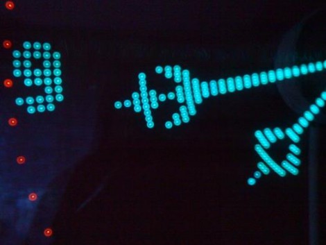
[Kizo] built an extraordinary persistence of vision clock. The design uses a PC cooling fan to spin the propeller-like PCB. As it goes around, a hall effect sensor synchronizes the illumination of the LEDs to draw the display. Power for the rotating electronics is transferred wirelessly via a transformer on the base and coil on the spinning board. The final version uses an ATmega324 microcontroller running at 20 MHz and has an IR receiver for changing the settings. The 3000 lines of code bring a lot of bells and whistles, including a menu system with a huge amount of settings from tweaking the clock display, to font selection for scrolling messages. Take a look at the demo after the break. The double-sided board looks like it’s pretty difficult to etch at home, but as you can see from the forum post (translated), [Kizo] did a great job on this build from start to finish. Continue reading “Spinning POV Clock Done Oh-so-right”

Open Source Pick-and-place

This is a vacuum tweezers head for an open source pick-and-place. Those are the machines that professional printed circuit board manufacturers use to populate a circuit board with components before heading to the reflow oven. [Drmn4ea] built it with at-home rapid manufacturing in mind. The black orb on the left is a webcam for optical placement. The needle in the middle is an interchangeable vacuum-tool head. The motor on the right allows for different attachments to be swapped in automatically to suit a variety of parts.

This interfaces with a 3-axis CNC machine and should be easily compatible with a RepRap, Makerbot, or similar device. We wonder how he plans to handle reels of components, but this is a well-executed first step in the journey to a complete solution.

Want to see a professional pick-and-place at work? Check out one of SparkFun’s machines busy build a board after the break.

Continue reading “Open Source Pick-and-place”

Next Generation Arduino Manufacturing Problems?

[The Moogle] just got his new Arduino Uno; wow, that was fast. What should have been a happy unboxing turned sour when he took a close look at the board. It seems that it exhibits several examples of sloppy fabrication. The the lower-left image shows unclean board routing, a discolored edge, and a sharp tooth sticking out from the corner. The shield header shown in the upper left is not flush with the board, resulting in a weaker physical union and a crooked connection. There are vias that look like they’re not be centered in the solder mask, and areas where raw copper is exposed.

It saddens us to see this because the original Arduino boards were so well manufactured. Keep in mind that this may be an isolated case, and as of yet the company hasn’t been given the chance to swap out the board for one that has passed a more rigorous quality control inspection. But if you’ve already ordered one of your own, take a close look and make sure you’re satisfied with it upon arrival.

Not sure what we mean by next generation Arduino? Take a look at the new hardware that was recently unveiled.

Update: Here’s a direct response from the Arduino blog.

Update #2: [Massimo Banzi], one of the founders of Arduino, took the time to comment on this post. It details the organization’s willingness to remedy situations like [The Moogle] encountered and also links to the recent Arduino blog post.