Go The Extra Mile For Your LED Driver

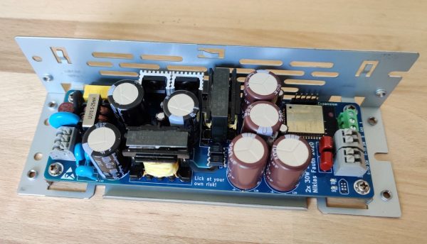
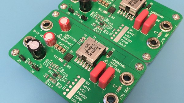
Addressable RGB LED strips may be all the rage, but that addressability can come at a cost. If instead of colors you expect to show shades of white you may the find less flickery, wider spectrum light from a string of single color LEDs and a nice supply desirable. Of course there are many ways to drive such a strip but this is Hackaday, not Aliexpressaday (though we may partake in the sweet nectar of e-commerce). [Niklas Fauth] must have really had an itch to scratch, because to get the smoothest fades for his single color LED strips, he built an entire software defined dual 50W switched-mode AC power supply from scratch. He calls it his “first advanced AC design” and we are suitably impressed.

Switched-mode power supplies are an extremely common way of converting arbitrary incoming AC or DC voltage into a DC source. A typical project might use a fully integrated solution in the form of a drop-in module or wall wart, or a slightly less integrated controller IC and passives. But [Niklas] went all the way and designed his from scratch. Providing control he has the ubiquitous ESP-32 to drive the control nodes of the supply and giving the added bonus of wireless connectivity (one’s blinkenlights must always be orchestrated). We can’t help but notice the PCBA also exposes RS485 and CAN transceivers which seem to be unused so far, perhaps for a future expansion into wired control?

Continue reading “Go The Extra Mile For Your LED Driver”

In-Depth Design Of A Flyback Converter

It is tempting to think of analogue and digital domains as entirely distinct, never to touch each other except like a cold war Checkpoint Charlie, through the medium of an ADC or DAC. In reality there are plenty of analogue effects upon digital circuitry which designers must be aware of, but there is one field in which the analogue and the digital are intricately  meshed. Switch mode power supplies use digital techniques to exploit the analogue properties of components such as inductors and capacitors, and can be astoundingly clever in the way they do this to extract the last fraction of a percent efficiency from their conversion. Thus their design can be something of a Dark Art, so it’s always interesting to have a good read explaining some of the intricacies. [James Wilson] has built a flyback step-up converter to power Nixie tubes, and his write-up follows the whole process in great depth.

This type of converter seems at first glance to be a simple step-up design with a transformer that has a primary and secondary, where in fact it relies on the collapse in magnetic field during the off period of its duty cycle to provide a spike in voltage and thus a step-up beyond that you’d expect from the transformer alone. The write-up takes us through all this starting from a theoretical perspective, and then goes further into the realm of component selection and the effects of component properties on the waveforms involved. If you have ever battled ringing in a switch mode power supply you may recognise some of this.

If this field interests you, then there is probably no better place to send you for a start than Jim Williams’ 1987 app note 25 for Linear Technology: “Switching Regulators for Poets“.

Fixing An Agilent Oscilloscope Power Supply

We should all be so lucky as [Salvaged circuitry], who scored a cheap Agilent oscilloscope from an online auction. Of course, its low price had a reason behind it, the ‘scope didn’t work. At fault was its power supply, the repair of which was documented in the video below.

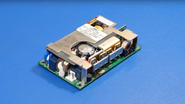
These ‘scopes have relatively straightforward 12 V power supplies, extremely similar to off-the-shelf parts. The video is an interesting primer in switch-mode power supply repair, as the obvious failure of the filter capacitor and a MOSFET is traced further to the PSU controller chip. We see a new capacitor mounted proud of the board to reduce the risk of heat damage, and then some careful solder rework to save some lifted pads.

The result, a working oscilloscope. Maybe we’d have hacked in another 12 V supply, but given that this is a piece of test equipment perhaps it’s best to stay as close to the original spec as possible. As a parting shot he shows us an equivalent power supply, and promises us a side-by-side test in a future video.

These ‘scopes aren’t as popular in our circles as the cheaper Rigol range, but it’s worth remembering that they also have a budget model.

Continue reading “Fixing An Agilent Oscilloscope Power Supply”

Another PC Power Supply Project

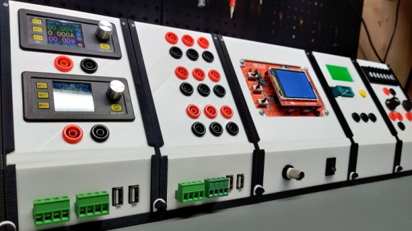
Economy of scale is a wonderful thing, take the switch-mode power supply as an example. Before the rise of the PC, a decent multi-voltage, high current power supply would be pretty expensive. But PCs have meant cheap supplies and sometimes even free as you gut old PCs found in the dumpster. [OneMarcFifty] decided to make a pretty setup for a PC supply that includes a very nice color display with bargraphs and other niceties. You can see the power supply in action in the video below.

The display is a nice TFT driven by an Arduino Nano. The project uses ACS712 current sensor modules, which are nice Hall effect devices that produce a linear output for current and have over 2 KV of voltage isolation.

Continue reading “Another PC Power Supply Project”

Review: The Riden RD6006W DC Power Supply Module

You may have seen the Ruideng range of programmable power supply modules from China: small and relatively inexpensive switch-mode buck converters, with microprocessor control and a front panel featuring a large colour OLED screen. Given 30 volts or so they can supply any lower voltage with the extra bonus of current limiting. They’ve been so successful over the several years they’ve been available that they’ve even spawned their own Chinese clones, and countless hacker projects, for instance on the DPS300X and DPS500X models.

Late last year a new module came from Ruideng, the Riden-branded RD6006 combines the basic idea of the previous modules with an extremely flexible front panel with full keypad and rotary encoder, creating something like the front panel to a decent bench power supply but without the accompanying power supply. I ordered one, waited for it to clear customs, took it to my bench, and reviewed it. Continue reading “Review: The Riden RD6006W DC Power Supply Module”

Build Your Own Active Load

When it comes to testing power supplies, it’s useful to have a dummy load to put the gear through its paces. While it’s possible to just use some old heating elements or other big resistors, an active load can provide more control over the process. [Charles Ouweland] found himself in need of just such a piece of gear, and decided to build his own.

Commercial units often pack in a raft of features, operating in different modes from constant resistance, constant power, and constant current. For [Charles]’s needs, just constant current would be fine, and thus the design progressed around this constraint.

The IRFP250 MOSFET specified in the build can dissipate up to 190W, but as it heats up, this is reduced. In this design, cooled by a heatsink and PC fan, [Charles] estimates 120W continous output is a safe limit. It’s combined with an LM358 op-amp and TL431A reference voltage source to act as a current sink, controllable between 0 and 10 amps.

We’re sure that the new hardware makes testing power supplies a cinch for [Charles], and it’s always good to have a strong understanding of the workings of your own test gear. We’ve seen open-source designs in this space, too!

Solving The Mysteries Of Grounding While Improving A Power Supply

Grounding problems and unwanted noise in electrical systems can often lead to insanity. It can seem like there’s no method to the madness when an electrical “gremlin” caused by one of these things pops its head out. When looking more closely, however, these issues have a way of becoming more obvious. In a recent video, [Fesz Electronics] shows us how to investigate some of these problems by looking at a small desktop power supply, modelling it in LTSpice, and reducing the noise on the power supply’s output.

While everything in this setup is properly grounded, including the power supply and oscilloscope, the way the grounding systems interact can contribute to the high amount of noise. This was discovered by isolating the power supply from earth ground using electrical tape (not recommended as a long-term solution) and seeing that the noise was reduced. However, the ripple increased substantially, so a more permanent fix was needed. For that, the power supply was modelled in LTSpice. This is where a key discovery was made: since all the parts of the power supply aren’t ideal, noise can be introduced from the actual real-life electrical behavior of some of the parts. In this case, it was non-ideal capacitance in the transformer.

According to the model, this power supply could be improved by adding a larger capacitor across the output leads, and also by increasing their inductance. A large capacitor was soldered in the power supply and an iron ferrule was added, which decreased the noise level from 100 mV to around 20. Still not perfect, but a much needed improvement to the simple power supply. If, on the other hand, you want to make sure you eliminate that transformer’s capacitance completely, you can always go with a transformerless power supply. That carries other risks, though.

Continue reading “Solving The Mysteries Of Grounding While Improving A Power Supply”