We’ve all likely watched an episode of “Star Trek” and admired the level of integration on the sick bay diagnostic bed. With its suite of wireless sensors and flat panel display, even the 1960s imagining of the future blows away the decidedly wired experience of a modern-day ICU stay. But we may be getting closer to [Dr. McCoy]’s experience with this radar-based respiration detector.
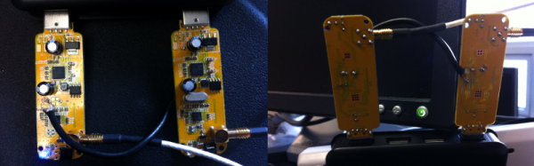
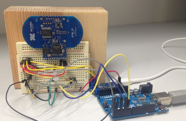
[Øyvind]’s build, which takes the origin of the term “breadboard” to heart, is based on a not-inexpensive Xethru module, which appears to be purpose-built for detecting respiration. The extra-thick PC board seems to house the waveguides internally, which is a neat trick but might limit how the module can be deployed. The module requires both a USB interface and level shifter to interface the 2.8V levels of the module to the 5V Arduino Uno. In the video below, [Øyvind]’s prototype simply lights an RGB LED in response to the chest movement it detects, but there’s plenty of potential for development here. We’ve seen a laser-based baby breathing monitor before; perhaps this systems could be used to the same end without the risk of blinding your tyke. Or perhaps better diagnostics for sleep apnea patients than an intrusive night in a sleep study lab.
Clocking in at $249 for the sensor board and USB interface, this build is not exactly for the faint of heart or the light of wallet. But as an off-the-shelf solution to a specific need that also has a fair bit of hacking potential, it may be just the thing for someone. Of course if radar is your thing, you might rather go big and build something that can see through walls.