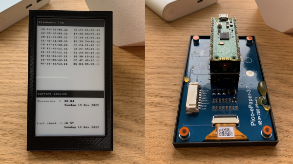
[Dmytro Panin] lives in Kyiv, Ukraine where there have been rolling blackouts to stabilize the power grid. To help keep track of when the blackouts might happen, be they planned or emergency, and to get more information on how long the blackouts last, [Dmytro] has created a blackout logger.
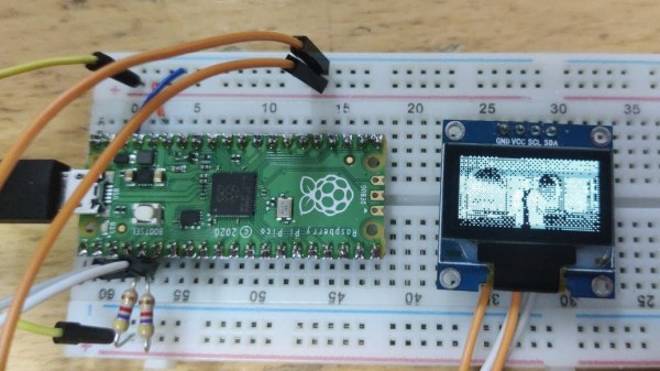
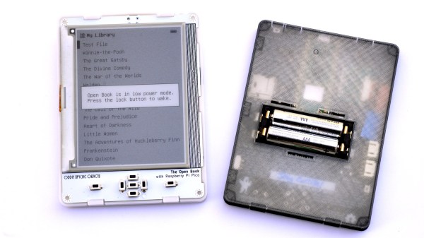
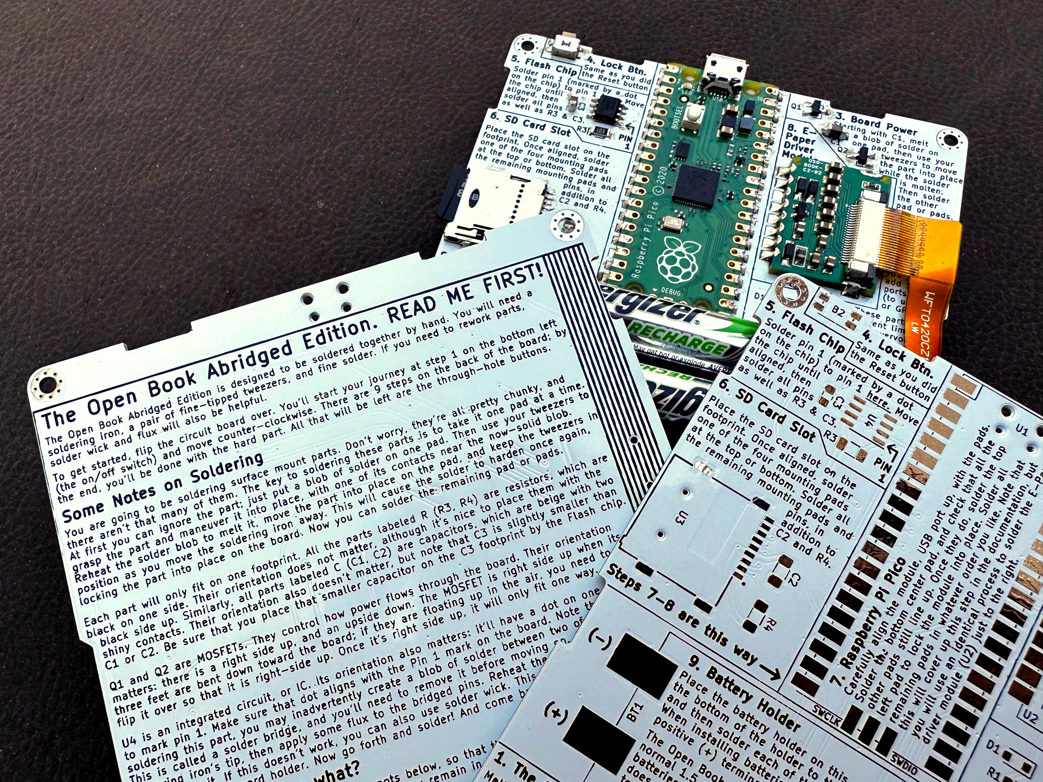
The build consists of a Raspberry Pi Pico that connects to a DS3231 real time clock (RTC) with a Waveshare 3.7 inch eInk display which [Dmytro] puts into a custom 3D printed case. The RTC has it’s own small power supply, often times from a coin cell battery attached to the module, allowing it to keep time when the module and other devices attached to it are powered off.
The Raspberry Pi Pico is programmed to “poll” every 30 seconds, writing the current time to a file. Should the unit lose power, the last time, within a 30 second window, is available when power is restored and the unit wakes up again. Since the RTC has kept the current time, there is enough information to display the duration of the blackout. The eInk screen ensures that the information is readily available, even when there is no power.
War is not the only reason blackouts can occur and we’ve covered some issues with blackouts in Texas and California in the US.