
Do you like scientific calculators? Don’t bother answering that question, you’re reading Hackaday so we already know the answer. We also know you’re a fan of building things yourself and open source, which makes us fairly sure you’ll be just as interested in the recently announced ClockworkPi PicoCalc as we are.
On the surface, it looks like a chunky scientific calculator, though on further inspection you’ll note it comes equipped with a QWERTY keyboard. But open up the case and what you’ve really got is an elaborate carrier board for the Raspberry Pi Pico. The PicoCalc supports all variants of the microcontroller, but realistically we can’t think of any reason that you wouldn’t just use the latest version.
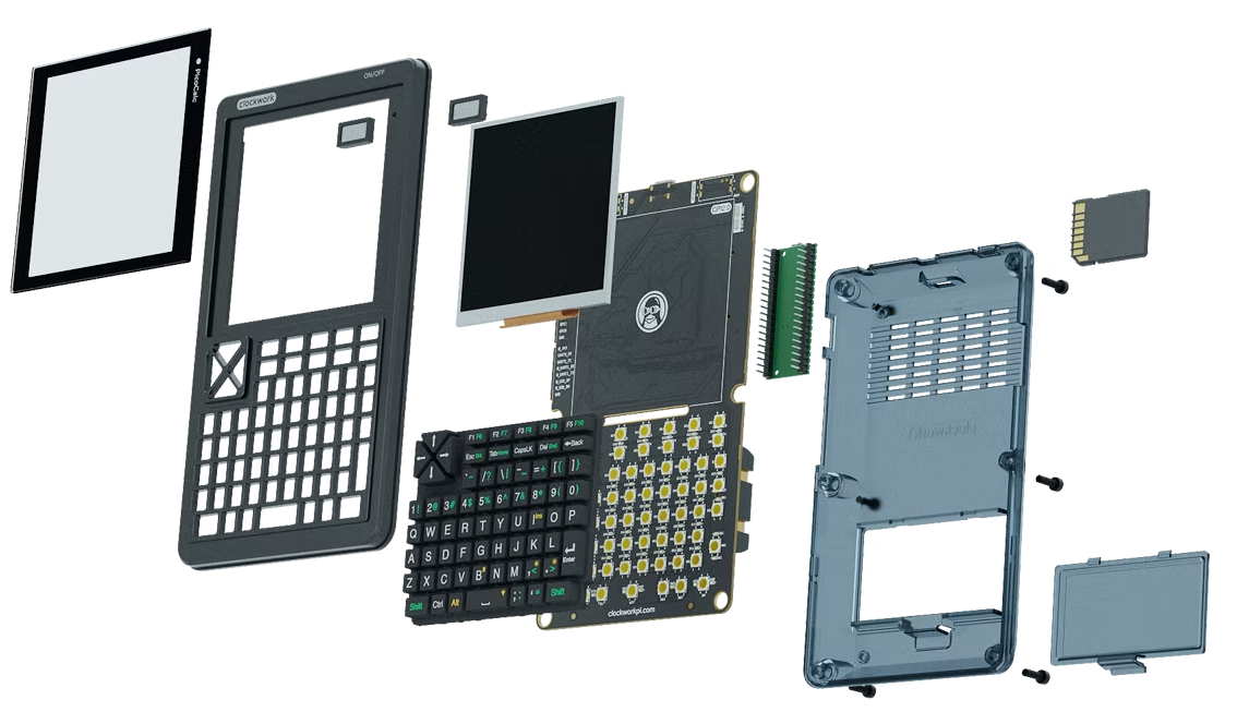 With the MCU connected, you’ll have access to the PicoCalc’s 320×320 4-inch IPS screen, backlit I2C-connected keyboard, SD card slot, 8 MB PSRAM, and dual PWM speakers. Power is provided by a pair of 18650 cells (which you’ll need to supply on your own), and the board has the necessary circuitry to charge them up over USB-C.
Everything is housed in an injection molded case, but the project page says all the necessary CAD files will be eventually be released under the GPL v3 so you can 3D print or CNC your own enclosure. For now though, the only thing of note that seems to be in the PicoCalc GitHub repository is a PCB schematic.
The software side of things is a little less clear. The page mentions a BASIC interpreter, MP3 playback, and support for various programming languages, but we get the impression that’s just a list of stuff you can run on the Pi Pico. There are a few images that clearly show the PicoCalc actually being used as a calculator however, so there may be an official firmware yet to be revealed.
The PicoCalc kit is on sale now, and will set you back $75 USD — which actually includes a first-generation Pi Pico, on the off chance that you don’t already have a few laying around. We’ve been impressed with the previous offerings from ClockworkPi, so assuming this new kit maintains that same build quality, it seems like a fair enough price.


