
When we think of programmable hardware, we think of FPGAs. But they’re not the only option. [Oliver Schmidt] has been exploring how the Raspberry Pi Pico can serve in such a role for the classic Apple II. The talk was presented at the KansasFest event this year, and it’s well worth diving into!
[Oliver] has developed A2Pico. It’s a series of Apple II peripheral cards that are based around the Raspberry Pi Pico, as you might have guessed. [Oliver] has been working in the area since 2021 with one [Glenn Jones], with the duo experimenting with connecting the versatile microcontroller directly to the slot bus of the Apple II. [Ralle Palaveev] then chimed in, developing the A2Pico hardware with solely through-hole components for ease of assembly.
A number of cards have been developed based on A2Pico, including a storage device, a Z80 CP/M card, and a specialized card to play Bad Apple on the IIGS. It’s all thanks to the versatility of the programmable I/O (PIO) peripheral inside the Raspberry Pi Pico. This device enables the Pico to be reprogrammed to handle all sorts of complicated tasks at great speed. This is particularly useful when using it to bit-bang a protocol or talk with another machine, and it serves perfectly well in this role. Basically, by reprogramming the Pico and its PIO, the A2Pico design can become any one of a number of different add-on cards.
It’s well worth diving into this stuff if you’ve ever contemplated building your own peripheral cards for 8-bit and 16-bit machines. We’ve seen some other great add-on cards for vintage machines before, too.
Continue reading “Using The Pi Pico As ‘Programmable Hardware’ For The Apple II”

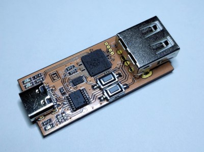 [ataradov] also offers us a complete board design with a RP2040 and a USB hub on it, equipped with USB sockets that completely free us from the soldering requirement; it’s


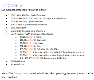 Despite the name it’s not a signal generator as we know it, as it’s not flexible in the signals it generates. Instead, it creates a dozen signals at more or less the same time — from square waves of various frequencies and duty cycles, to a PWM-driven DAC driving eight different waveforms, to Manchester-encoded data I2C/SPI/UART transfers for all your protocol decoder testing.
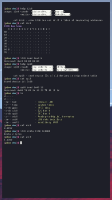 BreadboardOS is built on top of FreeRTOS. It’s aim is to enable quick prototyping with the Pi Pico. Don’t confuse operating system with a graphical environment — BreadboardOS is command-line based. You’d typically interface with it via a serial terminal emulator, but joy of joys, it does support color!


