Adding RS232 To A Multimeter The Hard Way

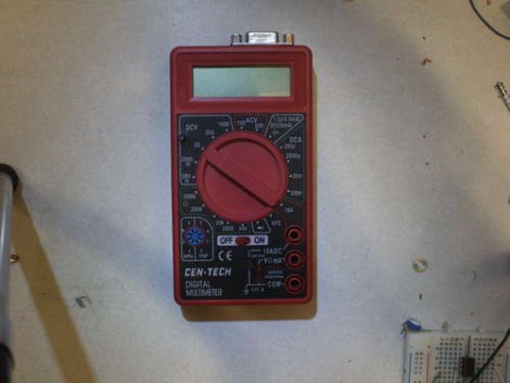
You might want to store information from a multimeter to be graphed over time. This comes with pretty much all of the high-end professional models. But if you buy a super cheap meter you can bet this isn’t an option. [Jazzzzzz] has found a way to pull the data from a $4 meter via RS232. It’s not impossible, but we definitely think he’s doing it the hard way. That’s because he’s not just tapping into a dormant feature. He’s actually adding a microcontroller to sample the data and push it via the RS232 protocol.

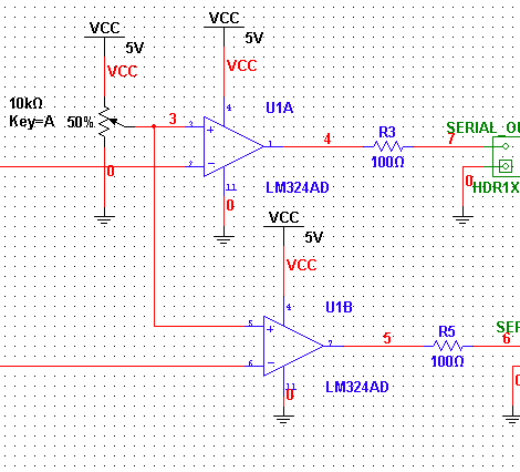
On the bright side, this is easier than building a multimeter from scratch. The sampling circuits are still being used, with a PIC 16F688 intercepting the signals as they enter the stock microcontroller. The signal he was after comes into the chip on just one pin, but to get the readings right on the PIC he had to use an OpAmp. That’s only part of the puzzle as he also needed a way to tell what the selector switch was set at. In the end, adding a potentiometer and reading its value let him calculate the position.

[Thanks Karl]

Making Oscilloscopes From ARM Development Boards

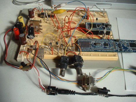
If you’ve got an ARM development board gathering dust in the corner of your shop, perhaps you could repurpose it as an oscilloscope. [Arend-Paul Spijkerman] was able to use an mbed and LPCXpresso as the hardware end of an oscilloscope. He didn’t use a standalone screen as a display, instead opting to push the scope readings from the hardware to a computer for display. This was greatly simplified by using StampDock as a basis for the GUI.

His circuit diagrams calls for an RS-232 connection for the LPCXpresso but not for the mbed. We’re not quite familiar enough with the mbed to know why, but perhaps those in the know can clue us in by leaving a comment. The probe connections are quite simple, each made up of a voltage divider and a pair of diodes. But the breadboard above looks much busier because it has two oscilloscope circuits built on it, and there’s a 10 MHz clock and a 4040 ripple counter which were used to provide a test signal.

LG TV Hacking Via Serial Connection Or IR Codes

[Brendan Robert] has been sending us forum thread links outlining the things he’s learned while hacking LG televisions. They were a bit hard to follow for the uninitiated, so we asked if he could give us an overview of what he’s been working on. Not only did he do that, but he made a little Hackaday shout-out seen above by adding the skull and cross-wrenches as one of the menu overlays.

He’s using a TV as his computer monitor, which he picked up at a discount because it was a display model. Without the original remote, and wanting to have features like power-saving mode which is standard on monitors but not on this TV, he decided to see what he could accomplish. A couple of things made this quite a bit easier. First, there’s an RS232 port built into the back which removes the need to investigate and solder your own onto the board. Secondly, since LG built on the Linux kernel for the set, you can download some of the firmware sources from their website.

What he came up with is a script that will find and communicate with the TV over the serial connection. The test script used during development polled every possible command, looking for valid return values. Once [Brendan] established which commands work and what they do, he was able to take command of the unit, writing scripts to adjust brightness based on the ambient light in the room as seen from the computer’s webcam. Make sure you check out the sub-pages to his post that detail the brightness adjustments, stand-by functionality, custom overlay graphics, and the extra commands he uncovered.

PIC Based Frequency Counter

Here’s a PIC based frequency counter that outputs the count via an RS232 serial connection. [Oakkar7] tipped us off about it after seeing the AVR based counter we featured yesterday. This project is a bit older and a bit dirtier.

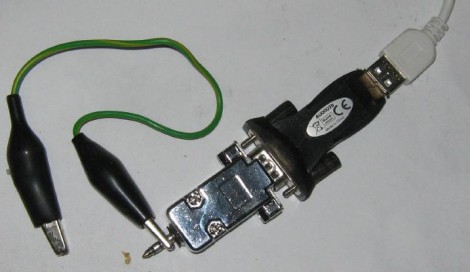
Inside the metal DB9 housing you’ll find just seven parts. The most important is a PIC 16F628 which handles both the counting and the serial communications. We’re not quite sure how it’s managing to talk to that USB-to-Serial converter without some type of level conversion. Since this microcontroller is not a dedicated counter chip a little bit of trimming must be done to bring the accuracy into spec. There’s also some physical trimming involved. In order to get everything to fit into the small enclosure the circuit was free-formed without a PCB or protoboard and the case of the DIP chip had to be ground down just a bit. As for the readout, a simple script can grab the data and display it in a terminal.

[via Piclist]

Unlocking RS232 Serial Comm On A Multimeter

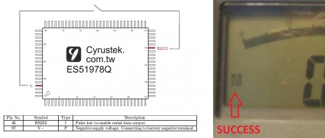
[Craig] cracked open a multimeter to unlock RS232 serial communications that can be used for data logging. There’s a couple of things that make this possible. First of all, the multimeter’s processor is not covered in a black epoxy blob, leaving the pins exposed for hacking. Second, the chip model is known and [Craig] was able to get his hands on the datasheet. One of the pins enables serial output when pulsed low. Touching it to V- even turns on an RS232 icon on the display, as seen above. To make this accessible without opening the case a momentary push button can be added, as well as connector for signal output, and a bit of parsing on the PC side to handle incoming data.

Android Talks Pulsewave

Serial communications are a mainstay of digital computing. They don’t require much physical infrastructure and they exist in variations to fit almost any application. The behaviour of serial communications lines, varying from high to low voltage in a timed pattern, is analogous to a 1-bit DAC. Using a whole DAC for serial communication would be a waste in most cases, but the [RobotsEverywhere] team found an exception which you may have encountered already.

Since the audio output of the Android is accessible and addressable, [RobotsEverywhere] wrote source code to use the left and right channels as separate serial communication lines. This circumvents the need to bust into the device and muck about with the hardware which is great if you want a no-risk hack that allows communications to an RS232 port. Any hardware on which you can write to the DAC (and control the sampling rate) is a potential target.

There are some external electronics required to convert the audio signal to TTL, but it’s not very complicated–a couple of comparators and change. You can see it in action after the break.

As a bonus, when you’re done for the day you can plug in your headphones and listen to the soothing poetry of pulse waves all night long.

Continue reading “Android Talks Pulsewave”

Cheap And Easy SMS Via GSM For Your MCU

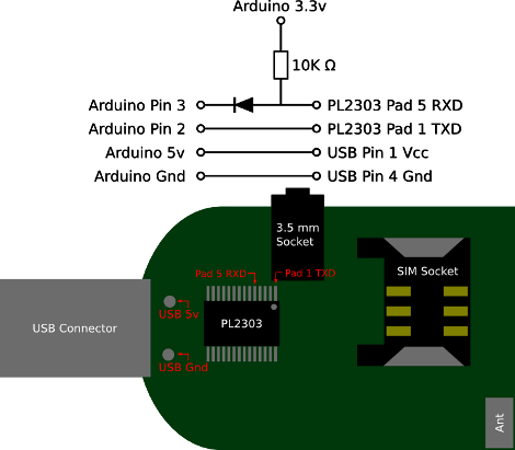
Non acronym version of the title: send and receive text messages via cell phone communication towers using an Arduino or other microcontroller. “We’ve been doing that for years!” you cry, well yes, technically. But [Fincham] lays it outs simply; commercial offerings are expensive and finding a cell phone that uses RS232 now a days is getting difficult, so a new way of doing the same old is necessary. The good news is USB GSM modems are readily available, cheap, and only require a few interface pins to get them talking with an Arduino. In fact, the image above is all you need.