Arduino Aquarium Lights

[Kalle Hyvönen] just finished building his own aquarium lights. He used four powerful soft-white LEDs, mounting them on a pair of heat sinks to keep things cool. Now he could have just connected them to the power supply and plugged it into the wall, but instead he included is own controller. An Arduino drives the switch-mode power supply, offering dimming thanks to PWM, and the ability to automatically switch the light on and off using an RTC chip with a battery backup. The sketch includes the ability to alter the lighting schedule and other variables by sending serial commands through a USB connection. This protocol is detailed with comments in his sketch.

We’ve seen a lot of interesting aquarium light projects. This one that uses heat from the LEDs to warm the water is one of our favorites. Others are full of features like this version that includes a moonlight mode. But Arduino enthusiasts don’t have to look far to find offerings like this PAR meter build, or this aquarium light controller library which can be recreated using the ubiquitous controller board.

Hacking An AC Outlet Timer For Project Use

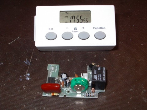
[Karl] needed a programmable real-time clock for one of his projects. He considered adding an RTC chip, LCD screen, and some buttons for use with a microcontroller. That’s not necessarily hard, but it takes time and can be considered a project in itself. Instead, he headed to the hardware store to look for a cheap solution. He was able to get this AC outlet timer for a song. It’s got everything he needs; twenty programmable on/off events, a calendar to track time and day of week, and a user interface made up of a low-power LCD and four buttons. He cracked open the case and patched into the electronics for use with any project.

You can see the solder-tab battery in the middle of the board (green coin-cell). That actually runs the timer circuitry and display. It’s topped off when the unit is plugged into mains, but [Karl] ended up replacing it with a much higher capacity AA rechargeable battery. The device works just like a thermostat, using very little power and driving a relay at the appropriate time. Batteries in thermostats seem to last forever and we can expect the same performance from this device. [Karl] rerouted the trigger signal from the relay to his own 2N2222 transistor. This way the device can switch loads running at voltages other than its own 1.2V operating level.

Stock timers are great. They’re mass-produced which makes them cheap, and you can do some interesting stuff with them. We really enjoyed see this other mechanical version hacked for hydroponic use.

Very Accurate Clock Can’t Be Read Accurately

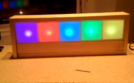
[Martijn] is showing off his new clock which he calls a Light Spectrum Clock. We like to look of it, using RGB LEDs in five squares that remind us of some of those LED coffee table builds. From left to right this shows the week, day, hour, minute, and second. Simple, right?

We had to smile a little bit when looking through his write up. He chose an Arduino nano as a controller, using a TLC5940 chip to drive the LEDs. But it is the inclusion of a DS1307 real-time clock that we find amusing. It will keep quite accurate time (not quite as well as the DS3232 but still respectable) but the fuzzy display technique makes telling the time accurately an impossibility. But like other color-based clocks, that’s part of the fun. The real reason for using an RTC chip is that they usually include battery-backed operation so that you can shut off the LEDs when you’re not around and the clock will continue to tick.

You can watch the seconds pass by as fading colors in the clip after the break.

Continue reading “Very Accurate Clock Can’t Be Read Accurately”

Chrono-tomic Shield Helps Your Arduino Keep Perfect Time

chronotomic-arduino-shield

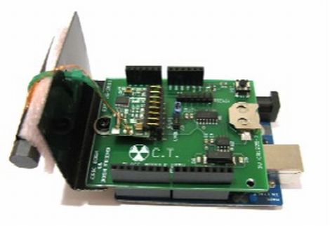
[Josh] and his lab partner [Eric] needed a final project for their Embedded Systems Design class, and thought that designing an Arduino shield would be a cool idea. They noticed that there are plenty of ways to get an Arduino to keep time, though none that they knew of utilized WWVB (Atomic Time) signals directly.

The Chrono-tomic Arduino shield uses a C-MAX radio to demodulate the WWVB signal, demodulating it and passing it along to a PIC16F1824 microcontroller. The PIC decodes the data frame and verifies it is valid, sending the time to an MCP79410N real-time clock module.

We can hear the “Yo dawg I herd you like microcontrollers so I put a microcontroller on your microcontroller shield” jokes already, but the pair says that they offloaded the time processing to the PIC in order to let the Arduino focus on whatever tasks it has been delegated. The Arduino code merely needs to request the time from the RTC whenever it is required, rather than deal with the decoding itself.

Is it overkill? Perhaps – though we think it heavily depends on your application and configuration. We can certainly conjure up situations where it would be useful.

Bobuino: Arduino Based On ATmega1284 + Goodies

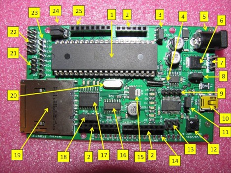
[Erik] wrote in letting us know that he just completed development of the Bobuino, a Arduino based on an ATmega1284. That chip is nice and beefy, most notably for having 16 KB of SRAM but it also boasts 4 KB of EEPROM, and 128 KB of program memory.

But the upgraded chip isn’t the only thing that it brings to the table. It’s easy to spot the on-board SD card slot in the image above. Also of note is the battery-backed DS1307 real time clock with a jumper that will route the square wave output to one of two pins on the microcontroller.

This design is compatible with standard Arduino shields thanks to the familiar pair of pin sockets, and can still be programmed via the USB socket. Since the AVR chip has more IO than normal there’s also pin headers to break out the PORTC pins, for a JTAG connector, and for an RS232 port.

Simple Clock Uses RTC Chip And Character Display

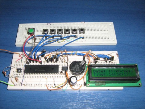
[Giorgos Lazaridis] just finished building a simple clock on a breadboard. It uses a common real time clock chip, the DS1307. This is less expensive that its full-featured older brother, the DS3232. The difference between the two is that the 1307 requires an external 32.768 kHz crystal and it is not temperature compensated. This means it will not be quite as accurate over the long-haul (it may wander as much as one minute per month), but it still blows the accuracy of using a microcontroller as an RTC out of the water and includes a backup battery which will keep time when the rest of the circuit is switched off.

This design uses a PIC 16F1937 to display the time and date on a 16×2 character LCD screen. Six buttons are dedicated to incrementing one specific chunk of data (ie: one button changes the year, another the day, etc.). A seventh button can be held down when using the other six in order to decrement the setting. We’re always interested in how the button code is written. [Giorgos] did share his code, but he wrote it in assembly so it’s of little use to us as we tend to stick to C code.

See the walk through video after the break.

Continue reading “Simple Clock Uses RTC Chip And Character Display”

Warm Tube Clock, Take 2

warm_nixie_v2

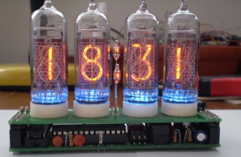
[Mure] wrote in to let us know he has put the finishing touches on the second iteration of his Warm Tube Nixie clock. We featured his original creation here last year, and while many things remain the same, he has still found a few things that he was able to improve on.

The first notable feature is the new real time clock. Instead of using a discrete crystal to keep time and a temperature sensor for compensation, he has opted to use a DS3231 RTC IC. It is far more accurate than the crystal, and it features a built-in temperature sensor as well. The alarm functionality has been simplified too, moving the controls into firmware rather than having to use a sliding switch to do so.

With the mainboard redesign, it would have been easy to leave behind the nixie “shields” he created for his first clock, but with a focus on interoperability, he chose to make this clock fully compatible with version one’s shields and vice versa.

While the changes aren’t groundbreaking, it’s nice to see a project like this undergo continued refinements. If you want to build a clone of this clock, [Mure] has made sure that all of the schematics and source code are available on his site.

Continue reading to see a brief video demo of the clock in action.

Continue reading “Warm Tube Clock, Take 2”