Adding A Serial Trigger To A Logic Analyzer

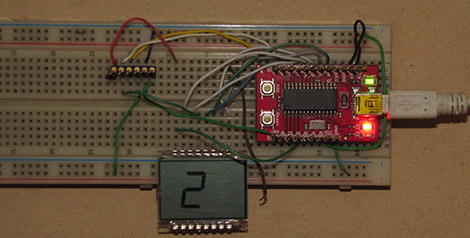
If you’re attempting to debug a serial bus with a bare-bones logic analyzer, you’re going to have a bad time. Most of the inexpensive analyzers available don’t have a serial pattern trigger, or a way to start recording data after a specific pattern of bits comes down the pipe. [Neil] sent in a great little project that adds a serial trigger to these analyzers, we’ve got to hand it to him for designing such a useful board.

[Neil] designed a small board featuring a CLPD that converts serial data to parallel data. By setting the trigger condition of the logic analyzer to any 24-bit pattern he wants, it’s possible for [Neil] to sniff a serial bus exactly when he wants to.

The circuit is quite minimal, basically just a 100-pin CLPD and a bunch of 0.100″ header pins. It’s a useful tool, and although we couldn’t find the board file to make our own, we’re sure [Neil] will be providing that shortly.

Getting A Console And Quake II Running On A Raspberry Pi

Those Raspberry Pi boards are flying into the mailboxes of tinkerers all around the globe, so our tip line is currently awash in a deluge of Raspi hacks. Here’s two that came in over the weekend:

First up is [reefab]’s port of Quake II for the Raspberry Pi. The build is based of Yamagi Quake II and is mostly playable. The Quake III port for the Raspberry Pi is old hat, but we’re happy to relive the pulse-pounding action of Quake II any day.

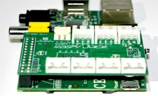
Next up is [Joonas]’ take on getting a serial console up and running with the Raspi. The Raspberry Pi has a UART serial console on its 26-pin header, but you can’t just connect those pins to a serial port. To shift the +/- 12V down to the 3.3 Volts the Raspi can understand, [Joonas] used a MAX3232 – the 3.3 Volt version of everyone’s favorite RS-232 transceiver. With a breadboard and a couple of caps, it’s easy to connect your Raspi to a serial console. Neat.

GSM Modem Means Wireless Serial Connections

By now, most of us have seen have seen one of those GSM to wi-fi hotspot bridges. They’re interesting devices, and being able to carry a small wireless router with you at all times is very handy. Surprisingly, we haven’t seen many builds featuring these portable wireless hotspots, something probably due to the effort in breaking out a serial connection on these devices. The people at Open Electronics decided to build their own small serial-enabled cell phone modem, a boon to someone wanting a serial connection to any place with a cell tower.

The Open Electronics GSM/GPRS/GPS modem includes a header for an FTDI USB serial chip and a GSM module. Plug one into your computer and after a few short commands into a terminal, you’ve got a serial connection to nearly anywhere in the world.

The cost of the setup is a little high – around 80€ or $100 USD – and you probably should buy more than one so you can also receive data. While it is more expensive than the XBee wireless boards we see often, this GSM modem isn’t limited to the 300 foot range of the XBee. We’ll probably see this in a high altitude balloon before too long.

Build Your Own USB To Serial Dongle

[Johan von Konow] found that he was using an FTDI USB-to-Serial chip in a lot of his projects and wanted to have an easy prototyping component on hand to facilitate this. What he came up with is the extremely small USB to serial dongle seen above. The copper fingers are designed to plug into your USB port. And if you’ve got an unused thumb drive (we’ve got a 128mb version that’s been collecting dust for years) it would make a perfect enclosure for the device.

He’s using an FT232BL chip in a LQFP-32 package. That’s got 0.8mm pitch so make sure you’ve got a steady hand, a fine tipped soldering iron, and some solder wick on hand. The 0603 passives might also give you a bit of a run-around during soldering, but all-in-all we think everyone will be able to successfully assemble this with a little bit of practice. The chip is the most expensive component at just under $6. But the good news is that the board is single sided and only needs one jumper wire making for very little drilling and easy home fabrication.

If you’re putting in a parts order, we’d recommend getting doubling the amount of resistors and capacitors. Chances are you’ll drop a few and nary will they be seen again. We also highly recommend looking into [Gerrit’s] surface mount component clamp.

Chipcon CC1110/CC1111 Serial Bootloader

[Joby Taffey] just rolled out a serial bootloader for the Chipcon CC1110/CC1111 processors. The project is called CCTL and aims to make prototyping with the Girltech IM-ME a bit less tedious. Up until now firmware for the device had to be pushed in with a GoodFET or TI proprietary programmer which was quite slow. But this bootloader makes it possible to push your code via the chip’s serial port at 115200 baud. But the pretty pink pager isn’t the only device using these chips and to prove it [Joby] send this picture of all the electronics he has on hand running this architecture.

Once the 1KB CCTL bootloader has been flashed to the chip, a serial port or USB to Serial converter can be used as a programmer. [Joby] warns that the Chipcon processors are not 5V tolerant so you need to either use a 3V serial converter or add a level converter into the mix.

CCTL provides the features you’d expect from a bootloader. It uses the chip’s watchdog timer to guard against failure due to broken code. And there is an upgrade mode available at power up. Instruction for use are included in the Github repo linked at the top.

Vintage VT100 Terminal Computing…with A Beaglebone

decbox

A cool little project came our way, which we thought might be of interest to some of you vintage computer buffs. [Joerg Hoppe] wrote in to share a DEC VT100 terminal he resurrected in a novel fashion.

His “DECBox” system was created with a Beaglebone, which he uses to run a wide array of PDP11/VAX terminal emulators, thanks to the SIMH project. [Joerg] constructed an expansion shield for the Beaglebone that provides several UART connections, enabling him to connect it to his DEC terminal over a serial interface. Since he added several serial plugs to the Beaglebone, he can even run multiple emulator installations in parallel on different terminals without too much trouble.

[Joerg’s] efforts are mainly for a vintage computer display he is constructing, but setting up such a system of your own should be no problem. If you happen to have one (or more) of these boxes sitting around collecting dust, this would be an easy way to get them all up and running without bulky external hardware, since the Beaglebone tucks nicely into the rear expansion slot on a VT100.

Be sure to check out his site for more details on how his DECBox software package works as well as for more pictures of vintage terminal goodness.

Android 3.1 Devices Have USB Host Mode. Here’s How To Use It.

With the coming of Android 3.1 you finally have the option of using the device as a USB host. This may be through a USB OTG (On-the-Go) adaptor, but nonetheless it’s a feature which was sorely missed until now. [Manuel] put together a guide on using Android as a USB host. As you can see, his example hardware is an Arduino board but this is applicable with just about any device.

The tutorial implements a test app for the Android device where a slider will set the brightness of the Arduino’s on-board LED. The Arduino sketch is nothing special, it just reads data received on the UART. This means that it doesn’t care if it’s connected to an Android, PC, OSX, or Linux system, it goes about its business until the RX interrupt updates the data variable.

This will greatly simplify a lot of projects we’ve seen, such as this message scrolling belt buckle. That used extra hardware to make the Arduino the host, a step that is now necessary.