FT-2232 Bridges Python And I2C/SPI

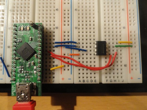
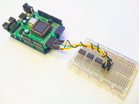
You might already have the hardware on hand to easily interface I2C and SPI devices with Python scripts on your computer. The board seen above is an FT-2232 breakout board. These chips are often used to facilitate JTAG programming via USB, but they have other features that might be useful to you as well. The chip has a Multi-Protocol Synchronous Serial Engine (MPSSE) which can speak the I2C and SPI protocols, you just need to know how to active them in your code.

[Craig] makes this easy with his MPSSE Python wrapper. Simply install his module, and you’ll be able to import all the commands you need. He demonstrates reading the data out of a 1 MB SPI flash memory chip. This could be used for a lot more, including debugging peripherals à la the Bus Pirate, or reprogramming chips to add to your projects (we’re thinking font arrays and sprites for displays, or look-up tables).

If you’re not aware, these FTDI chips were the go-to for USB support for a long time. We’ve got a guide for bit-banging using this hardware. Lately more chips have become available with USB hardware built-in. They’re quite useful and cost-effective, especially with the availability of open-source stacks like the LUFA project.

Controlling Shift Registers Via SPI

Hack a Day’s very own (and very prolific contributor) [Mike Szczys] put up a great tutorial on how to drive shift registers with an SPI interface.

[Mike]’s earlier tutorial of the 595 shift register goes through the functions of a shift register pin by pin. In a 595, bits for each position in the register are sent over one at a time. Most microprocessors have an Serial Peripheral Interface, and using an SPI bus means a lot less mucking about.

An ATmega168 was used for this build, although most Atmel chips can be made to work as an SPI master device. There are just three wires connecting the microcontroller to the shift register – SER, SRCLK, and RCLK. Like any other shift register setup, the build can be expanded by connecting the QH’ pin of the first 595 to the SER pin of the second.

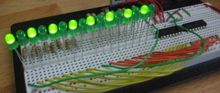
[Mike] graciously made all the code for his build available. The video after the break is a 16-bit binary counter, a good stopping point before [Mike] rebuilds his Larson scanner/Cylon/Kitt, moving away from a PWM-based build to a register-based one.

Continue reading “Controlling Shift Registers Via SPI”

Recovering A Corrupted EEE PC BIOS

recovering_eeepc_bios

[Jeremy] had an ASUS EEE PC 1000HE netbook on his hands which had succumbed to a corrupted BIOS. In most situations, people replace a motherboard when the BIOS is damaged beyond repair, but considering the price of motherboards, especially those built for portable devices, he simply refused to go that route.

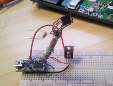
Instead, he took it apart and did a little investigation to find out what SPI flash chip ASUS used in the netbook. With that information in hand, he put together an SPI flash programmer using a breadboard and a DLP-USB1232H USB to UART module. He couldn’t program the flash chip in-circuit, so he had to desolder it and deadbugged it onto his programmer. Using a few Linux-based flashing tools, he was able to reprogram the chip with a functioning BIOS in short order, saving him from a costly motherboard replacement.

While some motherboard manufacturers have built in secondary BIOS chips to prevent the need for this sort of recovery, it’s nice to know that the process is relatively straightforward, provided you have some basic soldering and Linux skills.

This also isn’t the first time we’ve seen someone recover an EEE PC from the brink – if you’re looking for an Arduino-based alternative, be sure to check this out.

What Has 114 LEDs And Is Always Running?

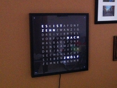
The answer, of course, is a word clock. This is actually [Eric’s] second version of a word clock. Like the first one, it uses 114 LEDs to back light the words on the display.

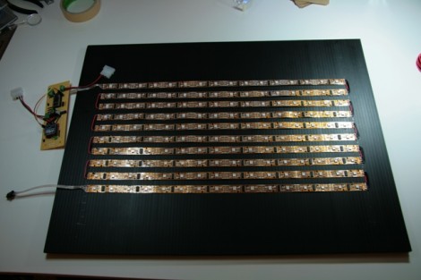
In his first iteration he used an Arduino to drive a Charlieplex array of lights. It was an 11 by 10 grid, plus four LEDs to display the in-between minutes as dots at each corner of the clock face. This time around he’s still using an Arduino, but the lights have seen a huge upgrade. In one of his build pictures you can see the reel of RGB led modules which have two RGB LEDs and an HL1606 driver on each segment. These are SPI controlled, making them easy to hook up, using just a few data and power bus rails. Check out the test video after the break that shows what this grid is capable of.

In case you can’t figure out what time is displayed above, you might check out an English version of a Word Clock face to help in your own build.

Continue reading “What Has 114 LEDs And Is Always Running?”

Want 2 Megabytes Of SRAM For Your Arduino?

How much memory do you really need? We suppose it’s not really our place to judge how you misuse use memory in your projects. But we do appreciate the clean and orderly technique that [Eric Rogers] uses to add multiple SPI SRAM chips to an Arduino.

The heavy lifting is done with a CPLD shield called the Amani 64. It intercepts the SPI calls from the Arduino to an SRAM chip, and translates the address information to find the appropriate data on a collection of 23K256 devices. These chips are inexpensive, and using several of them provides a savings over choosing a single SPI addressable chip with a larger memory size.

The best part is that the flexibility of the CPLD allowed [Eric] to devise an addressing system that takes advantage of unused bits in the Arduino’s SPI data transfer functions. When using a single 23K256 chip, there are four write functions that waste a total of six bits. He devised a method to inject addressing data into these unused bits, allowing him to address up to 64 different memory chips for a potential of 2 MB of storage. The CPLD pulls out this injected address and subsequently writes or reads the bank of SRAM chips.

Looking for other SRAM upgrade options? Here’s another one that uses multiplexing to decrease the address lines necessary to add memory.

Digital Picture Frame Reverse Engineering

coby_frame_hack

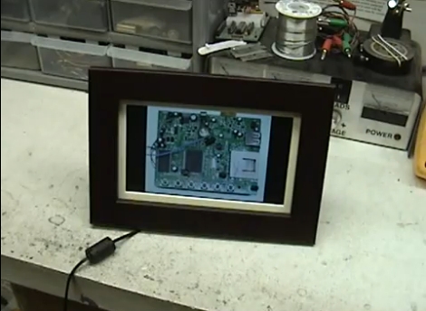
A few months ago [Jason] got his hands on a free Coby DP700WD digital picture frame and thought it would be fun to hack. After realizing that the frame did not run any sort of Linux-based OS he figured his options were pretty limited, but he gave it a shot anyways.

The frame came with a set of built in images, and his goal was to swap them out for pictures of his own. He started by trying to read data from the frame’s serial flash chip, but found that the processor was preventing him from doing so. He de-soldered the chip from the frame, mounted it on a makeshift breakout board, and started reading up on SPI.

He was eventually able to read the device’s flash chip and swapped out the built-in images with his own. After a bit of trial and error, he was able to replace the frame’s boot screen with his own custom image as well.

If you are looking to do something similar, be sure to swing by his site – all of the tools and code he used to hack his frame are available for the taking.

Continue reading to see his modified picture frame in action.

Continue reading “Digital Picture Frame Reverse Engineering”

RF Control From Just About Any Device

[Mirko] is working on a library that will allow you to add RF control to just about any device. The only requirement is that the device be capable of running a Linux kernel, and that it have a few GPIO pins available. One example is fairly straight forward, a Netgear router. Many, if not most routers run a Linux kernel natively and most have solder points on the board for unused IO pins so patching into the hardware is very straight forward. Less obvious and much more impressive is the hack seen in the image above. [Mirko] built an SD card adapter cable and uses the contacts in the card reader to bit bang four-wire SPI to communicate with that RF module.