VFD Tube Clock Built Using Protoboard And Free-formed PSU

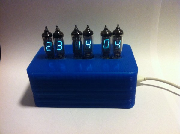
[James Glanville] wrote in to show of his latest tube project. It’s a clock using six IV-3 VFD tubes. In addition to the tube displays the project prominently features a blue 3D printed case which hides away all the guts of the build including the Stellaris Launchpad which drives the clock.

Speaking of guts, you’ll want to look through a few of [James’] other posts on the project. His first write-up on this clock shows off the protoboard and point-to-point soldering that makes the tubes work. To help simplify things he went with a MAX6921 VFD driver chip. He mounted it dead-bug style on its own piece of protoboard and then soldered all of the necessary connections to the larger hunk hosting the tubes. There’s also an interesting post that details the switch mode power supply which ramps the USB 5V power all the way up to the 50V used to drive the displays.

If you like this you should check out the first VFD clock he built. We featured it a while back in a links post.

Build Your Own Dumb USB Power Strip

diy-usb-power-strip

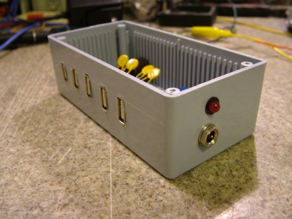
Here’s a USB charging center which [Kenneth Finnegan] built using parts from his junk bin. We’d like to reiterate our claim that he must have the most magical of junk bins (the last thing we saw him pull out of it was a 24-port managed Ethernet switch).

The jack on the side accepts the barrel connector from a 12V wall wart. [Kenneth] mentions that the 2.1mm jack is a standard he uses in all of his projects. Inside there’s a switch mode power supply that provides the regulated 5V to each USB port. We really like the fact that he added some protection; diy is no fun if you end up frying your beloved multi-hundred dollar devices. The yellow components are polyfuses which will cut the power if 600 mA of current is exceeded. This works great for almost all of his devices, but his iPod 4G doesn’t like the system. It sees the voltage dip just a bit and stops charging entirely.

Building A Bipolar Supply From A Boost Converter

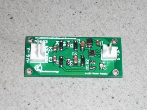
This DC-DC Bipolar PSU was developed for use with a guitar effects pedal. [Obsolete Technology] needed to source both positive and negative 15V. This is pretty easy to do if you’re converting from mains, but he wanted a solution that could work with a lower-voltage AC/DC wall wort or even from batteries.

The part that pulls it all together is the LT3467. It’s a switching power regulator which offers a range of features configured by the layout of a handful of external passive components. It can put out 80 mA on each line (positive and negative). Also extremely useful for this application is the chip’s high frequency operation. Depending on the version, it switches at 1.3 or 2.1 MHz. This is high enough that it will not introduce audible noise into the audio system.

We’ve got an exercise bike whose negative supply for the LCD is blown. We’re going to try build this circuit, trimming it for our voltage needs, and get the contrast working again.

[Thanks Olli]

Repairing A Junked Signal Generator

We must be walking past the wrong dumpsters because we certainly haven’t encountered equipment like this just waiting to be salvaged. [Shahriar] found an HP 8648C Synthesized Signal Generator while he was ‘dumpster diving’ and set out to fix the malfunctioning lab equipment. He posted a 1-hour video on the project, which you can find embedded after the break. The actual fix happens in the first half, the rest of the video is spent testing the resurrected device.

The back corner of the case has been dented, which may be the reason this has been thrown out. When it is first powered it emits an unpleasant screeching noise and the user interface doesn’t do anything. [Shahriar] says he recognizes the sound as a malfunctioning switch-mode power supply. Sure enough, when disconnected from the main board it still makes the noise. It turns out there’s a huge electrolytic capacitor the size of a stack of poker chips which has come loose from the PSU board. When it’s resoldered the device fires up as expected.

Now how are we going to find a digital capture oscilloscope that just needs to have its PSU reassembled?

Continue reading “Repairing A Junked Signal Generator”

Switch Mode Breadboard Supply From A PTH08080

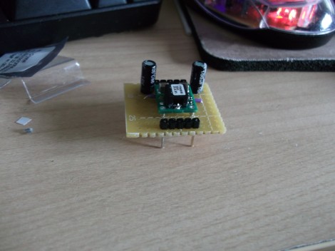
[Ben] wanted a switch mode power supply for his breadboard. He ordered a PTH08080 module which is made by Texas Instruments. The spec sheet would make it a great choice for him, but he was not happy to learn that the pinout doesn’t conform to the 0.1″ spacing used by solderless breadboards. His solution was to make a breakout adapter from some protoboard.

The PTH08080 can source up to 2.25A. It accepts 4.5-18V input and can output 0.9-5.5V. The best part is the efficiency that a switch mode supply achieves compared to linear regulators. This design adds in two capacitors which are suggested in the application circuit from the datasheet (PDF). Notice that there are two headers on the breakout board. One supplies power and ground to the breadboard. The other gives him a place to connect the adjustment resistor used to select the output voltage. This connects between one pin on the PTH08080 and GND. [Ben] plans to upgrade the design by included a precision trimpot for easy output voltage adjustments.

Another Switch Mode Regulator Swap For The Raspberry Pi

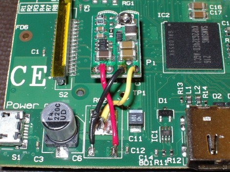
[Karl Lunt] is working to slim the Raspberry Pi current draw as much as possible. The first step in his journey was to replace the linear voltage regulator with this switch mode version. It’s a step-down voltage regulator circuit with a tiny footprint and a matching price tag (about $10) made by Pololu. It’s small enough to be mounted in the empty space between the LCD ribbon connector and the main processor.

The project was based on the hack we saw at the end of June. But we give much more credit to [Karl] for removing the old part in a safer way. He clipped the two small leads on the bottom of the old part, then used a beefy iron to sufficiently heat the large pad before removing the body of it. With the old part out of the way it’s just a matter of connecting the three wires in the right configuration.

This cut consumption by about 50 mA. He’s hoping to do more by removing the on-board LEDs. His goal is a draw of under 250 mA in order to make it last a reasonable amount of time when running from batteries.

Raspberry Pi Power Regulator Transplant Reduces Power Consumption

If you want to run your Raspberry Pi from something other than a mains power converter, and you’ve got some courage to spare, this hack is right up your alley. [Tom] wrote in with a switch mode power replacement for the RPi’s stock linear regulator. This is the first hack we’ve seen where the RPi’s on-board hardware is being altered and that’s where things get a little scary.

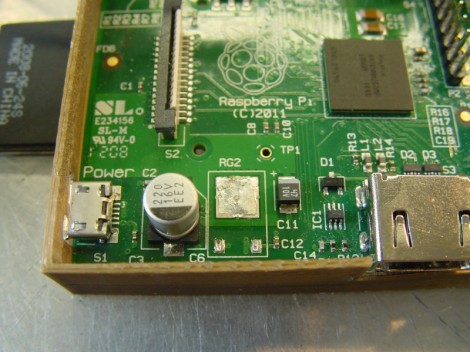
The first thing done was to remove the linear regulator, leaving the unpopulated RG2 footprint seen above. Apparently a rework station wasn’t available as the technique they used describes holding the board up by gripping the regulator with tweezers, then blasting it with a hot air gun. It makes us a bit queasy because the processor chip has a solder footprint you don’t want to mess with.

But apparently all is still well. With the wasteful linear regulator gone a pair of 5v and 3.3V switch regulators inject voltage through the GPIO header. Initial tests show a savings of around 25% but we’d imaging this varies greatly based on load.