
People say they don’t make em’ like they used to, and while this isn’t always the case, it’s certainly true that old vices rarely die with time. This doesn’t mean they can’t use a refresh. [Marius Hornberger] recently backed that up when he decided to restore an old vice that had seen better days.
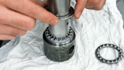
When refreshing old tools, you’ll almost always start the same: cleaning up all the layers of grease and ruined paint. The stories that each layer could tell will never be known, but new ones will be made with the care put into it by [Marius]. Bearings for the tightening mechanism had become worn down past saving, requiring new replacements. However, simply swapping them with carbon copies would be no fun.
[Marius] decided to completely rethink the clamping mechanism, allowing for much smoother use. To do this was simple, just machine down new axial bearings, design and print a bearing cage, machine the main rod itself, and finally make a casing. It’s simple really, but he wasn’t done and decided to create a custom torque rod to hammer in his vicing abilities. Importantly, the final finish was done by spraying paint and applying new grease.
Old tools can often be given new life, and we are far from strangers to this concept at Hackaday. Make sure to check out some antique rotary tools from companies before Dremel!


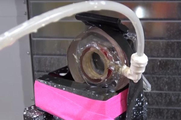
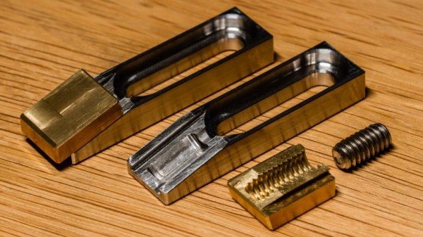
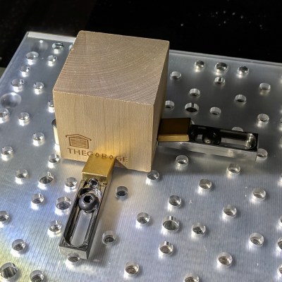 The usual way to secure a piece of stock to a fixturing table is to use top-down clamps, which hold the workpiece from the top and screw down into the table. However, this method limits how much of the stock can be accessed by the cutting tool, because the clamps are in the way. The most common way around this is to mount a vise to the table and clamp the workpiece in that. This leaves the top surface completely accessible. Unfortunately, [Kevin]’s benchtop Roland MDX-450 has a limited work area and he simply couldn’t spare the room. His solution was toe clamps, which screw down to the table and have little tabs that move inwards and downward. The tabs do the work of clamping and securing a piece of stock while maintaining a very low profile themselves.


