When tubes were king, you could go to a drugstore with a box full of them from your TV. There would be a tester that would tell you what tubes were bad and, of course, you could buy the replacements for them. That kind of tube tester was pretty simple. If you wanted to really know how to design with a tube or test its parameters, you were much better off with a curve tracer like the Tektronix 570 that [tomtektest] shows off in two recent videos that you can see below.
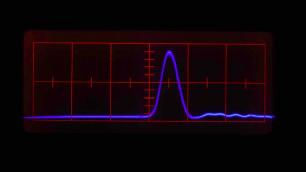
That piece of kit fell into [Tom’s] lap thanks to an observant delivery driver. The 1955 instrument is very similar to a semiconductor curve tracer but, of course, has the ability to provide much higher voltage for the tubes. The basic idea is that the X axis sweeps from a few volts up to 100s of volts. The vertical scale will show the plate, screen, or grid current. From those curves you can learn a lot about the characteristics of the tube.