2D Printed Tachometer For A Lathe

If you ever wanted a reason to have DC lighting pointed at the spinny part of your mill and lathe, [Bill] tells a great story. One day, he noticed the teeth on his lathe chuck would change color – red, then blue, then red. His conclusion was the fluorescent lights above his workbench was flashing, as fluorescent lights normally do.

Imagine if the teeth on [Bill]’s chuck weren’t painted. They would appear stationary. That’s usually a bad thing when one of the risks of using a lathe is ‘descalping.’ Buy an LED or incandescent work light for your shop.

This unique effect of blinking lights got [Bill] thinking, though. Could these fluorescent lights be used as a strobe light? Could it measure the RPM of the lathe?

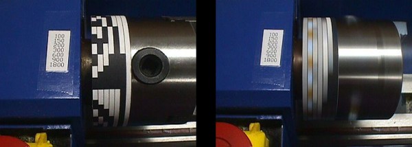
And so began [Bill]’s quest for a 2D printed lathe tachometer. The first attempt was to wrap a piece of paper printed with evenly space numbers around the chuck. This did not work. The flash from his fluorescent bulb was too long, and the numbers were just a blur. He moved on to a maximum-contrast pattern those of us who had a ‘DJ phase’ might recognize immediately.

By printing out a piece of paper with alternating black and white bands, [Bill] was able to read off the RPM of his chuck with ease. That’s after he realized fluorescent lights blink twice per cycle, or 120 times a second. If you have a 3″ mini-lathe, [Bill] put the relevant files up, ready to be taped to a chuck.

Need Timing Diagrams? Try Wavedrom

When working with anything digital, you’re going to end up reading or writing a timing diagram before long. For us, that’s meant keeping (text) notes, drawing something on a napkin, or using a tool like Inkscape. None of these are ideal.

An afternoon’s search for a better tool ended up with Wavedrom.

Just so you know where we’re coming from, here’s our list of desiderata for a timing diagram drawing solution:

  • Diagrams have a text-based representation, so their generation can be easily scripted and the results versioned and tracked throughout project development
  • Command-line rendering of images, because we like to automate everything
  • Looks good
  • Simple to use for common cases, but flexible enough to do some strange stuff when needed
  • Output modifiable when absolutely necessary: SVG would be nice

Basically, what we want is graphviz for timing diagrams.

Wavedrom nails four out of these five at the moment, and has promise to cover all of the bases. Give the online editor demo a try. We found it intuitive enough that we could make simple diagrams without even reading the fine manual. The tutorial has got you covered for more esoteric use cases.

foo

Clearly, some good thought has been put into the waveform description language, WaveJSON; it’s mostly readable and makes the essentials quick and easy. Because you can also enter straight SVG, it leaves the door open for full-fledged lunacy.

Wavedrom is written in JavaScript, and built for embedding in webpages; that’s the way they intend us to use it. On the other hand, if you want to run your own local version of the online editor, you can download it and install it locally if you’d like.

Our only quibble is that the standalone, command-line application wouldn’t generate images without the GUI on our Arch system. (Looks like there are some Google Chrome dependencies?) Otherwise, we think we’ve found our solution.

There are other applications out there. Drawtiming looks good, but we can’t quite get our head around the file format and the graphic output isn’t as flexible as we’d like: it only outputs GIF and we’re more into SVG because it can be edited easily after the fact.

There are font-based solutions that let you “type” the timing diagrams. We found Xwave and “Timing Diagram Font“. These work but aren’t particularly flexible; if you want something to happen at odd times, you’re out of luck. Plus, it just feels like a dirty hack, as if that were a bad thing.

Latex users can use tikz-timing, which makes sketching out your timing diagrams as much fun as laying out a very complex table in Latex (that is: not fun at all). On the other hand, it looks good, is ultimately flexible, outputs PDF, and would be scriptable if someone put the time in to write a nice frontend.

So for the next little while, we’re trying out Wavedrom.

What do you use for making timing diagrams?

Improving Active Loads

[Texane]’s job requires testing a few boards under a set of loads, and although the lab at work has some professional tools for this it seemed like a great opportunity to try out the Re:load 2. It’s a nifty little active load that’s available can of course be improved with an injection of solder and silicon.

While the Re:load 2 is a nice, simple device that can turn up to 12 Watts directly into heat, it’s not programmable. The ability to create and save load profiles would be a handy feature to have, so [Texane] took a Teensy 3.1 microcontroller and installed a resistor divider in front of the Re:load’s amplifier. A simple script running on a computer allows [Texane] to set the amount of current dumped and automate ramps and timers.

There is a more fundamental problem with the Re:load; the lowest possible current that can be dumped into a heat sink is 90mA. [Texane] replace the amplifier with a zero-drift amp that brought that 90mA figure down to 7mA.

Of course the Re:load and Teensy 3.1 are sold in the Hackaday store, but if you’re looking for a ready-built solution for a computer-controlled active load you can always check out the Re:load Pro, a fancy-smanchy model that has an LCD. The Pro costs more, and [Texane] just told you how to get the same features with the less expensive model we’re selling, though…

DIY Bearing Puller

DIY Car Wheel Bearing Puller

Cars are the greatest. They get you to where you need to go… most of the time. They can also let you down at the worst moment if a critical part fails.  Wheel bearings get a lot of use while we drive and [Dmitriy] found out the hard way how quickly they can fail. Instead of getting cranky about it, he set out to change the damaged bearing himself. In the process he made a pretty neat DIY bearing puller.

Some wheel bearings, on the front of a 2WD truck for example, are only held on by one large nut and easily slide off the spindle. This was not the case for the rear of [Dmitriy’s] AWD Subaru. The rear bearings are press-fit into a bearing housing. These are hard to remove because Outer Diameter of the bearing is actually just slightly larger than the Inner Diameter of the bearing housing. This method of retaining parts together is called an ‘interference fit‘.

BearingPuller2

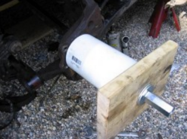
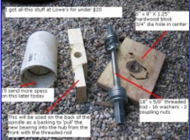
[Dmitriy’s] gadget uses one of Hackaday’s favorite simple machines, the screw, to slowly force the bearing out of its housing. It works by inserting a threaded rod through the bearing and bearing housing. Each side has a large washer and nut installed as well as a PVC pipe spacer providing support for the threaded rod. As the opposing nuts are tightened, one washer presses against the bearing and the bearing slowly slides out of the housing. Installation of the new bearing is the same except the tool is reversed to press the bushing into the housing.

Continue reading “DIY Car Wheel Bearing Puller”

dremel base station

DIY Super Accessory For Your Dremel

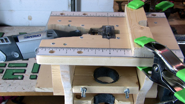
Little jobs require little tools and you can’t get much more littler than a Dremel. For his tiny tasks, [sdudley] has built a Dremel-powered base station that features a table saw, drum sander and router table. Overall, it is about one cubic foot in size and is almost entirely made from ‘1 by’ dimensional lumber. The Dremel power plant was actually used to make the base, specifically slowly removing material at the clamping points that hold the rotary tool secure to the base. The Dremel is held in an upright position and pokes out through the center of the table for both the drum sander and router configurations. To use this as a table saw, the Dremel is mounted almost horizontally on the base. A Mini Saw attachment has to be purchased for the table saw configuration but it does a great job at holding a vertically spinning saw blade.

After the break there’s a nice video of this tool’s use and assembly (it’s even worth watching just for the musical accompaniment that takes you on a wild ride through several genres of music). For those who want to make one for themselves, [sdudley] has made his part templates and assembly guide available in PDF format on his Instructables page. If you’re looking for something a little larger, check out this circular saw converted to a table saw.

Continue reading “DIY Super Accessory For Your Dremel”

The Four Thousand Dollar MP3 Player

[Pat]’s friend got a Pono for Christmas, a digital audio player that prides itself on having the highest fidelity of any music player. It’s a digital audio device designed in hand with [Neil Young], a device that had a six million dollar Kickstarter, and is probably the highest-spec audio device that will be released for the foreseeable future.

The Pono is an interesting device. Where CDs have 16-bit, 44.1 kHz audio, the Pono can play modern lossless formats – up to 24-bit, 192 kHz audio. There will undoubtedly be audiophiles arguing over the merits of higher sampling rates and more bits, but there is one way to make all those arguments moot: building an MP3 player out of an oscilloscope.

Digital audio players are limited by the consumer market; there’s no economical way to put gigasamples per second into a device that will ultimately sell for a few thousand dollars. Oscilloscopes are not built for the consumer market, though, and the ADCs and DACs in a medium-range scope will always be above what a simple audio player can manage.

[Pat] figured the Tektronicx MDO3000 series scope sitting on his bench would be a great way to capture and play music and extremely high bit rates. He recorded a song to memory at a ‘lazy’ 1 Megasample per second through analog channel one. From there, a press of the button made this sample ready for playback (into a cheap, battery-powered speaker, of course).

Of course this entire experiment means nothing. the FLAC format can only handle a sampling rate of up to 655 kilosamples per second. While digital audio formats could theoretically record up to 2.5 Gigasamples per second, the question of ‘why’ would inevitably enter into the minds of audio engineers and anyone with an ounce of sense. Short of recording music from the master tapes or another analog source directly into an oscilloscope, there’s no way to obtain music at this high of a bit rate. It’s just a dumb demonstration, but it is the most expensive MP3 player you can buy.

Fixing A Multimeter’s Serial Interface

[Shane] bought a multimeter with the idea of using its serial output as a source for data logging. A multimeter with a serial port is a blessing, but it’s still RS-232 with bipolar voltage levels. Some modifications to the meter were required to get it working with a microcontroller, and a few bits of Python needed to be written, but [Shane] is getting useful data out of his meter.

The meter in question is a Tenma 72-7735, a lower end model that still somehow has an opto-isolated serial output. Converting the bipolar logic to TTL logic was as easy as desoldering the photodiode from the circuit and tapping the serial data out from that.

With normal logic levels, the only thing left to do was to figure out how to read the data the meter was sending. It’s a poorly documented system, but [Shane] was able to find some documentation for this meter. Having a meter output something sane, like the freaking numbers displayed on the meter would be far too simple for the designers of this tool. Instead, the serial port outputs the segments of the LCD displayed. It’s all described in a hard to read table, but [Shane] was able to whip up a little bit of Python to parse the serial stream.

It’s only a work in progress – [Shane] plans to do data logging with a microcontroller some time in the future, but at least now he has a complete understanding on how this meter works. He can read the data straight off the screen, and all the code to have a tiny micro parse this data.