Precision Reference Puts Interesting Part To Work

Interesting parts make for interesting projects, and this nifty precision voltage reference has some pretty cool parts, not to mention an interesting test jig.

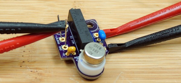
The heart of [Gaurav Singh]’s voltage reference is an ADR1399, precision shunt reference from Analog Devices. The datasheet makes for pretty good reading and reveals that there’s a lot going on inside the TO-49 case, which looks unusually large thanks to a thick plastic coat. The insulation is needed for thermal stability for the heated Zener diode reference. The device also has a couple of op-amps built in, one that provides closed-loop voltage control and another that keeps the internal temperature at a toasty 95°C. The result is a reference that’s stable over a wide range of operating conditions.

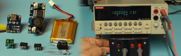
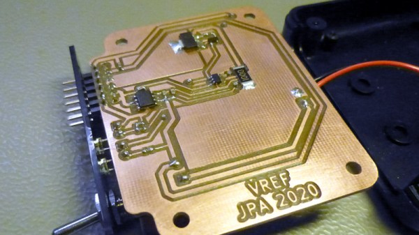
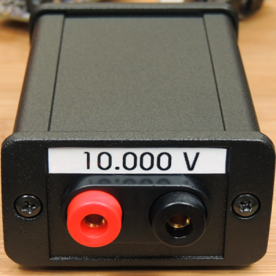
[Gaurav]’s implementation maximizes this special part’s capabilities while making it convenient to use. The PCB has a precision linear regulator that accepts an input voltage from 16 V to 20 V, plus a boost converter that lets you power it from USB-C. The board itself is carefully designed to minimize thermal and mechanical stress, with the ADR1399 separated from the bulk of the board with wide slots. The first video below covers the design and construction of an earlier rev of the board.

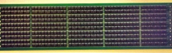
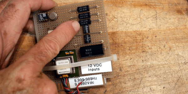
One problem that [Gaurav] ran into with these boards was the need to age the reference with an extended period of operation. To aid in that, he built a modular test jig that completed PCBs can be snapped into for a few weeks of breaking in. The jigs attach to a PCB with pogo pins, which mate to test points and provide feedback on the aging process. See the second video for more details on that.

Continue reading “Precision Reference Puts Interesting Part To Work”

The Best Voltage And Current Reference This Side Of A Test Lab

When you measure a voltage, how do you know that your measurement is correct? Because your multimeter says so, of course! But how can you trust your multimeter to give the right reading? Calibration of instruments is something we often trust blindly without really thinking about, but it’s not always an impossible task only for a high-end test lab. [Petteri Aimonen] had enough need for a calibrated current source to have designed his own, and he’s shared the resulting project for all to see.

The cost of a reference source goes up with the degree of accuracy required, and can stretch into the many millions of dollars if you are seeking the standards of a national metrology institute, but fortunately [Petteri]’s requirements were considerably more modest. 0.02% accuracy would suffice. An Analog Devices precision voltage reference driving a low-offset op-amp with a driver transistor supplies current to a 0.01% precision resistor, resulting in a reference current source fit for his needs. The reference is available in a range of voltages, his chosen 2.048 volts gave a 2.048 mA current sink with a 100 ohm resistor.

In a way it is a miracle of technology that the cheapest digital multimeter on the market can still have a surprisingly good level of calibration thanks to its on-chip bandgap voltage reference, but it never hurts to have a means to check your instruments. Some of us still rather like analogue multimeters, but beware — calibration at the cheaper end of that market can sometimes be lacking.

Zener Diode Tutorial

We always enjoy [w2aew’s] videos, and his latest on zener diodes is no exception. In it, he asserts that all Zener diodes are not created equal. Why? You’ll have to watch the video below to find out.

Zener diodes are one of those strange items that have several uses but are not as popular as they once were. There was a time when the Zener was a reasonable way to regulate a voltage inexpensively and easily. Unfortunately the regulation characteristics were not very good, and the power lost was very high. But that was sometimes a reasonable trade, compared to putting a pass transistor and the associated discrete circuitry in place to make a linear regulator. With the advent of chips like the 7800-series regulators, you can have a high-quality regulator with one extra wire and still keep your costs under $1. Even if you want to do better and go with a switching power supply, that’s easy now and not much more expensive.

Continue reading “Zener Diode Tutorial”

Homebrew Calibration For Test Equipment

If you work for a large company, you probably have test equipment that is routinely calibrated. Some companies have their own metrology labs and others send out to an external lab. In a garage lab, you are less likely to do calibrations and — in our experience — that isn’t usually a problem. Still, it is nice to be able to do at least a sanity check on your gear. Also, if you buy old test gear and repair it, it would be nice to be able to check it, as well. [IMSAI guy] built his own little calibration setup, adding to it over the years, and he shares the details in a recent video, which you can see below.

The board started out simply as one voltage regulator and some 0.01% resistors. Over time, though, he added a few more bells and whistles. The setup isn’t going to rival a NIST-traceable lab setup, but for your garage it is perfectly fine.

Continue reading “Homebrew Calibration For Test Equipment”

Precision Voltage Reference Source

[barbouri] found a few old (vintage?) parts from the early ’80’s while rummaging through his parts bin, and quickly spun out a small PCB to build a 10.000 V reference using these old ICs. Throwing together a small number of parts, he was able to build a source which might be good enough to use as a reference for another circuit or provide a quick calibration check for some of his bench instruments that have a resolution of 1 mV or maybe even 100 μV.

The AD584* pin programmable precision voltage references have been available since the ’80’s and offer four programmable output voltages of 10.000 V, 7.500 V, 5.000 V, and 2.500 V. The chip is laser-trimmed to ensure high accuracy and low temperature coefficient and requires just a few external components to function. It is available in TO-99 hermetically sealed metal can and 8-pin DIP variants. The “S” version of the device that [barbouri] used provides a temperature coefficient of 30 ppm/°C max over a -55 °C to +125 °C temperature range but other versions of the chip offer a better stability. Analog Devices seem to have discontinued the “L” version (pdf), since it is no longer listed in the current data sheet, but you can still get them from a few sources. The “L” version has a temperature coefficient of just 5 ppm/°C.

Using quality parts such as high stability resistors and TO-99 PTFE socket with gold-plated contacts, his observations confirm that the unit is stable within 30 μV, with a very slow voltage increase of a few microvolts every 6 hours. A 15 V linear regulator powers the device with input power coming from an external wall wart. A small aluminum enclosure houses the device, with two gold-plated 4 mm sockets for the output. If you would like to build your own, his board design is hosted on OSH park, or you can download the Eagle CAD design files. He’s posted all links on his blog post, and provides part numbers for all of the parts used. [barbouri] has been doing a good job of building handy devices for his work bench – check out his well-built milli Ohm Meter that we had featured earlier.

Stacking Voltage References To High Voltage Extremes

As children, we all probably had our ideal career paths. As an adult do you still harbor a secret desire to be an astronaut, or to drive a railroad train? Or have holders of other jobs become the people you envy?

As a Hackaday writer it’s probably not too controversial to admit a sneaking envy for the writers of semiconductor application notes. True, often their work consists of dry demonstrations of conventional uses for the products in question, but every once in a while they produce something off the wall and outside the device’s intended use, so out of the ordinary that you envy them their access for experimentation to the resources of a large semiconductor company.

Take Texas Instruments’ Application Report SBAA203, from May 2013. “Stacking the REF50xx for High-Voltage References” (PDF). A laboratory specialising in accurate measurement of high voltages had the problem that the stacks of Zener or avalanche diodes they were using as voltage references lacked both precision and stability, so investigated the properties of the REF5010 10V precision voltage reference.

You'll never be satisfied with a mere Zener diode again.
You’ll never be satisfied with a mere Zener diode again.

They found that by ignoring the device’s data sheet and directly connecting its output pin to its power pin, the REF5010 became equivalent to an ideal Zener diode. In this mode multiple references could be stacked in the same way as a real Zener diode, and very stable and high-precision voltage references could be created with very high voltages. They made a PCB with ten stacked REF5010s for a 100V reference, and then stacked ten of them for a 1000V reference. Leaving it for 24 hours to settle, they achieved a precision of +/- 2.5ppm, and after 3.5 months their average reading for the ten 1000V references they built was 1000.022V.

The 1000V reference would be impressive enough, but they weren’t finished. They built a series of boards holding 500 REF5010s for a 5KV reference, and stacked 20 of them to make a 100KV reference. These boards were mounted in a tower looking not unlike the Tesla coils we sometimes feature here. They note that it probably hits the record of simultaneous use of TI parts in a single device.

This may well be the first extremely high voltage precision reference to feature here at Hackaday, but we’ve certainly had our share of HV articles. Earlier this year we had a trio from [Steven Dufresne]: A conucopia of high voltage sources looking at ways to make your EHT, High voltage please, but don’t forget the current looking at selecting the right HV power supply for an application, and Wrangling high voltage looking at construction techniques.

Thanks [Nathan] for the tip.

Build A Precision Voltage Reference Box

So you just scored a vintage piece of test gear, or maybe you just bought a fancy new DMM (Hmm…We love that new multimeter smell!) But can it read voltage accurately? How can you be sure? Well, that’s why you should build yourself a voltage reference box.

Youtuber [Scullcom’s] latest video has you covered. Wants some specs? Sure. How does a precision 10v and 5v output with only ±0.025% and an amazing 2.5ppm/°C sound? That’s very impress for something you can cobble together yourself.  We find it interesting that he actually uses some ebay parts to pull off this build. The LiPo battery, USB LiPo charging circuit, and boost regulator are all sourced from ebay. Not to worry though, as these parts are only used to supply power to a 15 volt linear regulator. The real magic happens in the Texas Instruments REF102 precision voltage reference. You give it a decently clean 12-36 volts, and it will give you a 10 volt reference out.  These amazing chips are able to obtain such precision in part because they are calibrated (or more specifically “laser trimmed”) from the factory. A secondary output of 5 volt is achieved by using a differential amplifier.

Warning: The video after the break is a bit on the long side(43 mins), so you might want to make some popcorn. But we find [Scullcom’s] teaching style to be lovely, and he does a wonderful job of explaining the project start to finish, soup to nuts. Continue reading “Build A Precision Voltage Reference Box”