Hackaday Prize Semifinalist: Location Services For Robots

Robots of the future will be in the home, and ready to do whatever job we tell them to do. But they’ll need to know where they are within the house. Dead reckoning with accelerometers and gyroscopes are just a sufficient solution; what we really need is an indoor location service. For his Hackaday Prize entry, [Göran] is doing just that. He’s building a small device that will find its position with 10 cm precision, indoors.

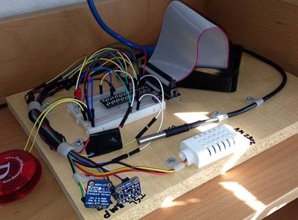
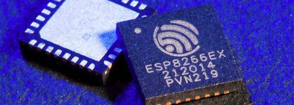
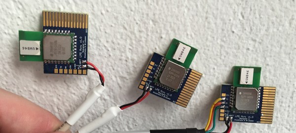
[Göran]’s LPS Mini is built around a very interesting part – the Decawave DWM100. It’s a module that uses an 802.15 radio to trilaterate the distance from several ‘anchors’ to a tag. This, by itself, gives the LPS Mini a navigation system with 10 cm precision. Even higher precision can be accomplished with an IMU gathering accelerometer, gyro, and compass data, and even further with a tiny altimeter. The result is a tiny board that knows exactly where it is.

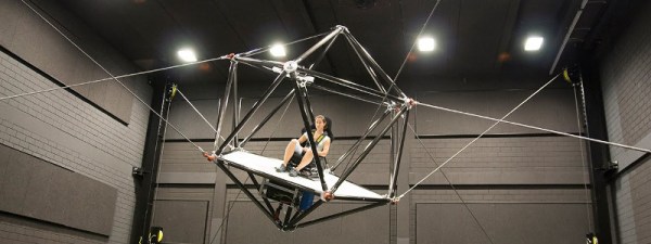
As far as practical uses go, these LPS Mini boards were used to move beds around an art exhibit at Hayward Gallery in London. While moving beds around an art gallery doesn’t sound like a game-changing invention, think about the uses for GPS in the 1980s – no one could have imagined a chip that would tell you where you are or that could keep a quadcopter on the right heading.

You can check out [Göran]’s video for the LPS Mini below.

The 2015 Hackaday Prize is sponsored by:

Continue reading “Hackaday Prize Semifinalist: Location Services For Robots”

Raspberry Pi Weather Station In Progress

[Jeremy Morgan] is building a weather station from scratch using a Raspberry Pi, and he has put together a nice write up that shows where he is at, and how it works. Currently, his setup is in the breadboard stage and is measuring humidity, temperature, pressure and light level using sensors that connect over one wire and I2C. He also shows how he is using Google Docs to store the data, by getting the Pi to write to a Google Spreadsheet over email: the Pi emails the data to Google every 30 seconds.

There is an analysis portion, with a Microsoft Azure web site that graphs the data over time. It’s a bit of a dogs breakfast (he might have used one interface technology for all of the sensors, for instance), but it is still a nice overview of the overall process.

Automatically channeling data into an easily accessible medium has been the target of many hacks going way back. We’ve seen a ton of companies pop up to help satisfy the need but between those and the hacked together (usually) open source solutions, there doesn’t seem to be a clear winner. What’s your favorite method of gathering and displaying data from projects like this onto the web? Let us know in the comments.

Arduino Teaches Morse Code

You may wonder why anyone would want to learn Morse code. You don’t need it for a ham license anymore. There are, however, at least three reasons you might want to learn it anyway. First, some people actually enjoy it either for the nostalgia or the challenge of it. Another reason is that Morse code can often get through when other human-readable schemes fail. Morse code can be sent using low power, equipment built from simple materials or even using mirrors or flashlights. Finally, Morse code is a very simple way to do covert communications. If you know Morse code, you could privately talk to a concealed computer on just two I/O lines. We’ll let you imagine the uses for that.

In the old days, you usually learned Morse code from an experienced sender, by listening to the radio, or from an audio tape. The state of the art today employs a computer to randomly generate practice text. [M0TGN] wanted a device to generate practice code, so he built it around an Arduino. The device acts like an old commercial model, the Datong D70, although it can optionally accept an LCD screen, something the D70 didn’t have.

You can see the project in operation in the video below. Once you learn how to read Morse code, you might want to teach your Arduino to understand it, too. Or, you can check out some other Morse-based projects.

Continue reading “Arduino Teaches Morse Code”

Cables And Winches Become An Awesome Simulator

Straight from the Max Planck Institute for Biological Cybernetics, and displayed at this year’s Driving Simulation Conference & Exhibition is the coolest looking simulation platform we’ve ever seen. It’s a spherical (or icosahedral) roll cage, attached to the corners of a building by cables. With the right kinematics and some very heavy-duty hardware, this simulation platform has three degrees of translation, three degrees of rotation, and thousands of people that want to drive a virtual car or pilot a virtual plane with this gigantic robot.

The Cable Robot Simulator uses electric winches attached to the corners of a giant room to propel a platform with 1.5g of acceleration. The platform can move back and forth, up and down, and to and fro, simulating what a race car driver would feel going around the track, or what a fighter pilot would feel barreling through the canyons of the Mojave. All you need for a true virtual reality system is an Oculus Rift, which the team has already tested with driving and flight simulation programs

An earlier project by the same research group accomplished a similar feat in 2013, but this full-motion robotic simulator was not made of cable-based robotics. The CyberMotion Simulator used a robotic arm with a cockpit of sorts attached to the end of the arm. Inside the cockpit, stereo projectors displayed a wide-angle view, much like what a VR display does. In terms of capability and ability to simulate different environments, the CyberMotion Simulator may be a little more advanced; the Cable Robot Simulator cannot rotate more than about sixty degrees, while the CyberMotion Simulator can turn you upside down.

The Cable Robot Simulator takes up a very large room, and requires some serious engineering – the cables are huge and the winches are very powerful. These facts don’t preclude this technology being used in the future, though, and hopefully this sort of tech will make its way into a few larger arcades.

We often see concepts come in waves. Earlier this week we featured a cable robot used to move pallets around a warehouse.

Continue reading “Cables And Winches Become An Awesome Simulator”

Learn Flip Flops With (More) Simulation

In the previous installment, we talked about why flip flops are such an important part of digital design. We also looked at some latch circuits. This time, I want to look at some actual flip flops–that is circuit elements that hold their state based on some clock signal.

Just like last time, I want to look at sequential building blocks in three different ways: at the abstraction level, at the gate level, and then using Verilog and two online tools that you can also use to simulate the circuits. Remember the SR latch? It takes two inputs, one to set the Q output and the other to reset it. This unassuming building block is at the heart of many other logic circuits.

circ5A common enhancement to the SR latch is to include an enable signal. This precludes the output from changing when the enable signal is not asserted. The implementation is simple. You only need to put an additional gate on each input so that the output of the gate can’t assert unless the other input (the enable) is asserted. The schematic appears on the right.

In the case of this simulation (or the Verilog equivalent), the SR inputs become active high because of the inversion in the input NAND gates. If the enable input is low, nothing will change. If it is high, then asserted inputs on the S or R inputs will cause the latch to set or reset. Don’t set both high at the same time when the enable is high (or, go ahead–it is a simulation, so you can’t burn anything up).(Note: If you can’t see the entire circuit or you see nothing in the circuit simulator, try selecting Edit | Centre Circuit from the main menu.)

Continue reading “Learn Flip Flops With (More) Simulation”

This Project Will Be Stolen

What do you get when you take a flight case from Harbor Freight, fill it up with random electronics junk, and send it off to a stranger on the Internet? The travelling hacker box. It’s a project I’m putting together on hackaday.io to emulate a swap meet through the mail.

The idea is simple – take a box of random electronics junk, and send it off to a random person on hackaday.io. This person will take a few items out of the box, replace those items with something sitting on their workbench, and send it off to the next person. This is repeated until the box is stolen.

Has something like this been done before? Yes, yes it has. The Great Internet Migratory Box of Electronics Junk was a thing back in the ‘aughts, with Hackaday (via Eliot) receiving a box (code name: Rangoon) from [John Park], before sending it off to [Bre Pettis]. The box subsequently disappeared. There were many migratory boxes of electronics junk, but most didn’t travel very far. Already the Travelling Hacker Box has 2,525 miles on its odometer, and plans are in the works for travelling 25,000 miles – the circumference of the Earth – before heading out of the United States.

If you’re wondering what’s in the box, here’s a mostly complete inventory. With the exception of a few items from the swag bag from the Open Hardware Summit last weekend, it’s mostly random electronics stuff I’ve had sitting around on my workbench and desk. The first recipient grabbed a few dev boards and replaced them with a Teensy LC and enough tubes to make a small amplifier.

The current plan for the Travelling Hacker Box is to bounce across the United States for the circumference of the Earth until departing for more exotic lands. There are people queued up to receive the box from across the world, and the box will eventually be hitting Europe, India, Africa, Asia, and Australia. Everyone is welcome to participate as it is passed from hacker to hacker as a migratory box of electronic toys.

Hackaday Dictionary: The ESP8266

In August of 2014, something new started showing up in the markets of Shenzhen, the hi-tech area of China where the majority of the world’s electronics components are made. This is the ESP8266, a WiFi SoC (System on a Chip) that can connect to 802.11b/g/n networks on the 2.4GHz band. It can be addressed with SPI or a serial connection, and has an AT command set that makes it behave rather like an old-style modem. Basically, it has everything you would need to connect a device to a WiFi network, with the ESP8266 chip itself handling the complicated business of finding, joining and transmitting/receiving over a WiFi network.

That’s nothing particularly new in itself: WiFi connection devices like the TI CC3000 have been around for longer, and do much the same thing. The difference was the price. While the TI solution costs about $10 if you buy several thousand of them, the ESP8266 costs less than $7 for an individual board that can plug straight into an Arduino or similar. Buy the chip in bulk, and you can get it for less than $2.

The ESP8266 is more than just a WiFi dongle, though: it is a fully fledged computer in itself, with a megabyte of flash memory and a 32-bit processor that uses a RISC architecture. This can run applications, turning the ESP8266 into a standalone module that can collect and send data over the Internet. And it can do this while drawing a reasonably low amount of power: while receiving data, it typically uses just 60mA, and sending data over an 802.11n connection uses just 145mA. That means you can drive it from a small battery or other small power source, and it will keep running for a long time.

It wasn’t an easy ship to write applications for in the early days, though: it was poorly documented and required a dedicated toolchain to work with. This made it more of a challenge than many hackers were comfortable with.  That changed earlier this year, though, when the Arduino IDE (Integrated Development Environment) was ported to the chip. This meant that you could use the much easier to write Arduino functions and libraries to write code for the chip, bringing it within reach of even the most casual hacker.

Continue reading “Hackaday Dictionary: The ESP8266”