Beginner Concepts: Designing Transistor Control Circuits

Need to switch something on or off using a microcontroller? Using a transistor is one of the best ways to do this, but how exactly do you design properly for transistor switching? [Ben Krasnow] put together a tutorial in which he does an excellent job of explaining the ins and outs of designing transistor control circuits.

We’ve embedded his twenty-minute video after the break. In it he talks about the use of transistors, the difference between NPN and PNP transistors, and the design specifics you need to know when working with them. We think that beginners will find [Ben’s] demonstration of how to calculates Hfe, which is the base current necessary to fully switch the transistor. If this is gibberish to you, have no fear. [Ben’s] instruction is clear and easily understandable.

The one thing we missed in the video is clarification about base current protection for PNP transistors. [Ben] mentions that there’s no easy circuitry that can be used on the base of a PNP  to regulate flow from the emitter to the base, but he doesn’t elaborate. Otherwise, it’s everything we could have wanted on the topic.

Continue reading “Beginner Concepts: Designing Transistor Control Circuits”

FET: The Friendly Efficient Transistor

If you ever work with a circuit that controls a decent amount of current, you will often encounter a FET – a Field-Effect Transistor. Whether you want to control a couple of powerful LEDs, switch a USB device on and off, or drive a motor, somewhere in the picture, there’s usually a FET doing the heavy lifting. You might not be familiar with how a FET works, how to use one and what are the caveats – let’s go through the basics.

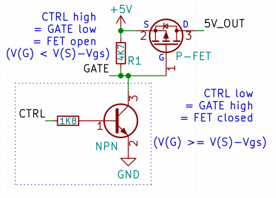
Here’s a simple FET circuit that lets you switch power to, say, a USB port, kind of like a valve that interrupts the current flow. This circuit uses a P-FET – to turn the power on, open the FET by bringing the GATE signal down to ground level, and to switch it off, close the FET by bringing the GATE back up, where the resistor holds it by default. If you want to control it from a 3.3 V MCU that can’t handle the high-side voltage on its pins, you can add a NPN transistor section as shown – this inverts the logic, making it into a more intuitive “high=on, low=off”, and, you no longer risk a GPIO!

This circuit is called a high-side switch – it enables you to toggle power to a device at will through a FET. It’s the most popular usecase for a FET, and if you’re wondering more about high-side switches, I highly recommend this brilliant article by our own [Bil Herd], where he shows you high-side switch basics in a simple and clear way. For this article, you can use this schematic as a reference of how FETs are typically used in a circuit.

Continue reading “FET: The Friendly Efficient Transistor”

Won’t Somebody, Please, Think Of The Transistors!

At what age did you begin learning about electronics? What was the state of the art available to you at the time and what kinds of things were you building? For each reader these answers can be wildly different. Our technology advances so quickly that each successive generation has a profoundly different learning experience. This makes it really hard to figure out what basic knowledge today will be most useful tomorrow.

Go on, guess the diode!

Do you know the forward voltage drop of a diode? Of course you do. Somewhere just below 0.7 volts, give or take a few millivolts, of course given that it is a silicon diode. If you send current through a 1N4148, you can be pretty certain that the cathode voltage will be that figure below the anode, every time. You probably also have a working knowledge that a germanium diode or a Schottky diode will have a lower forward voltage, and you’ll know in turn that a bipolar transistor will begin to turn on when the voltage between its base and emitter achieves that value. If you know Ohm’s Law, you can now set up a biasing network and without too many problems construct a transistor amplifier.

Continue reading “Won’t Somebody, Please, Think Of The Transistors!”

Switching: From Relays To Bipolar Junction Transistors

How many remote controls do you have in your home? Don’t you wish all these things were better integrated somehow, or that you could add remote control functionality to a random device? It’s a common starting point for a project, and a good learning experience for beginners.

A common solution we’ve seen applied is to connect a relay in parallel to all the buttons we want to press. When the relay is triggered, for example by your choice of microcontroller, it gets treated as a button press. While it does work, relays are not really the ideal solution for the very low current loads that we’re dealing with in these situations.

As it turns out, there are a few simple ways to solve this problem. In this article, we’re going to focus on using common bipolar junction transistors instead of relays to replace physical switches. In short, how to add transistors to existing electronics to control them in new ways.

Continue reading “Switching: From Relays To Bipolar Junction Transistors”

A 3D Printed Junction Transistor Model

Transistors are no doubt one of humankinds greatest inventions. However, the associated greatness brings with it unprecedented complexity under the hood. To fully understand how a transistor works, one needs to be familiar with some Quantum Mechanics! As perhaps any EE undergraduate would tell you, one of the hardest subject to fathom is in fact semiconductor physics.

Take your pick: Mathematical equations governing the various currents inside a BJT

A good place to start to comprehend anything complex is by having an accurate but most importantly, tangible model at hand. Semiconductors are hard enough to describe with elaborate mathematical tools, is a physical model too much to ask?

[Chuck] has designed, printed and explained the workings of a BJT transistor using a 3D printed model. We really like this model because it goes a long way to shed light on some of the more subtle features of BJT transistors for beginners.

For example, the simplest “electronic switch” model completely ignores the application of a transistor as a linear amplifier and cannot be used to explain important transistor parameters such as hfe (DC current gain Beta) or the VBE (voltage to forward bias the base-emitter junction). [Chuck’s] model on the other hand certainly offers better intuition on these, as the former can be linked to the length of the levers arm and the latter to the minimum force needed to rotate the lever. The Tee structure even signifies the combination of base current with the collector current during operation!

If physical models are not your thing, the classic pictorial depiction, the “Transistor Man” in the Art of Electronics might be of interest. If you’ve even outgrown that, its time to dig into the quantum mechanics involved.

Continue reading “A 3D Printed Junction Transistor Model”

Cheap, Easy To Build Robot For Beginners

Robotics kits are a great way to get folks , young and old, interested in hacking and learning the basics. Quite often, the cost puts them off – it’s no fun if you mess things up while learning how to put an expensive kit together. Many kits are too polished and that leads to beginners feeling that they’ll never be able to build something complex like a robot. The Shonkbot is what the team at Bristol Hackspace came up with for a robot that is obvious in its working and encouragingly easy to build, even for kids (with supervision).  To that effect, they completely avoided custom PCBs and laser cut bits. The Shonkbot is built from easily available parts and some commonly available materials. They aimed to build it for £5, but managed £15. With proper planning and time, they guess it can be brought down to £10.

The Shonkbot is built using an Arduino Nano, two stepper motors with their drivers, a 3xAA battery box and some bits and bobs. Assembly takes about an hour for a 10-year-old and then they can reprogram it in another workshop or at home. The “frame” of the Shonkbot is an old CD-ROM or DVD disk. Everything is hot glued to this frame. At the centre of the disk, a Sharpie is inserted and the Arduino code then allows the robot to draw on paper. Upgrades include adding an IR LED, a photo transistor and a buzzer to allow the Shonkbot to detect objects, or communicate with other Shonkbots. Build instructions are detailed in this document, and the code is available from the Github repository. Here is a photo album from their first build workshop which was held recently.

Thanks to [Matthew Venn] from the Bristol Hackspace for sending in this tip. Check the robot in action in the video below.

Continue reading “Cheap, Easy To Build Robot For Beginners”

Beginner Concepts: MOSFETs

[Moser’s] introductory guide to MOSFETs serves as a quick introduction for those unfamiliar with the parts. They fill a similar role as a bipolar junction transistor like the 2N2222, making it possible to switch large loads. But fundamentally they are different. Metal Oxide Field Effect Transistors have three pins for Drain, Source, and Gate instead of the Collector, Emitter, and Base that you may be used to. The Gate is the control pin for the device and offers a desirable advantage over bipolar junction transistors in that it is insulated from the channel. This means that much less current flows into the Gate when compared to the Base of a common transistor, saving power and providing protection to the logic circuitry.

Don’t fret if this makes your head spin. [Moser’s] writeup is short and to-the-point but it’s not watered down. You can get a basic overview and if you care to learn more, he’s linked to datasheets and has basic terminology that is easily clarified with a Google search. One of the most powerful tools that he’s included is the simple MOSFET and driver circuit diagram you see above. This makes it possible to switch incredibly large loads very quickly; the true power of the MOSFET.