Solar Panel Keeps Cheap Digital Calipers Powered Up

There’s no doubt that cheap digital calipers are useful, especially when designing 3D-printed parts. Unfortunately, cheap digital calipers are also cheap, and tend to burn through batteries quickly. Sure, you can remove the battery when you’re done using them, but that’s for suckers — winners turn to solar power to keep their calipers always at the ready.

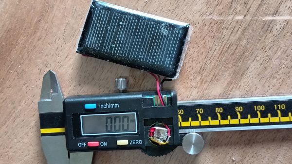
[Johan]’s solar upgrade begins with, unsurprisingly, a solar cell, one that just fits on the back of his digital calipers. Like most of these cheap calipers, this one is powered by a single 1.5 V LR44 button cell, while the polycrystalline solar cell is rated for 5 V, so [Johan] used a red LED as a crude voltage regulator. He also added a stack of fourteen 100 μF SMD capacitors soldered together in parallel. The 1206 devices form a 1,400 μF block that’s smaller than the original button cell so that everything fits in the vacated battery compartment. It’s pretty slick.

Given their agreeable price point, digital calipers are a tempting target for hacking. We’ve seen a ton of them, from accessibility add-ons to WiFi connectivity and even repurposing them for use as DROs. Ever wonder how these things work? We’ve looked at that, too.

Inside Digital Calipers

If you do any kind of machining, 3D printing, or PCB layout, you probably have at least considered buying a pair of calipers. Old-fashioned ones had a dial and were mechanical devices, but lately, digital ones have become quite affordable. We keep meaning to tear a set of ours apart to see what’s inside, but thanks to [learnelectronics], we don’t have to — the video below provides a fascinating look at what’s inside a cheap pair of Harbor Freight calipers.

Honestly, it doesn’t seem like it would be that hard to figure out how far down a bar you are. The trick is the caliper has to be super accurate. Oddly enough, the cheap calipers examined use capacitors as a sensing element.

There is a long flexible PCB stuck to the sliding part with conductive pads. The display unit is also a printed circuit and manages the battery, the display, and the other half of the capacitive sensor. If you want a more detailed explanation of how the sensor actually works, check out capsense.com. If you note, the pattern on the sliding part has traces that look like a square wave, and half have a different phase than the other half. These are the sine plates and the cosine plates. A 100 kHz signal flows through the capacitor, and it is possible to read the direction of travel and the amount of travel easily.

The calipers are very accurate, but it’s possible to improve them. A more practical project is to make them communicate with the outside world.

Continue reading “Inside Digital Calipers”

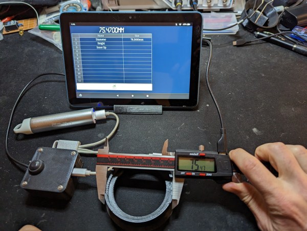
A digital caliper connected to a tablet computer

Custom Interface Adds USB And Wi-Fi To Digital Calipers

Although old-school machinists typically prefer the mechanical vernier scale on their trusty calipers, many users nowadays buy calipers with a digital readout. These models often come with additional features like differential measurements, or a “hold” function for those situations where you have to maneuver the instrument somewhere deep inside a machine. Another useful feature is a data link that lets you log your measurements on a computer directly instead of manually entering all the values.

The VINCA-branded caliper that [Liba2k] bought has such a data link feature, which requires a USB adapter that’s sold separately. There is a micro-USB connector on the tool itself, but instead of implementing a USB interface, this is used to carry a proprietary serial protocol — a design decision that ought to be classified as a felony if you ask us. Rather than buying the official USB adapter, [Liba2k] decoded the protocol and built his own interface called VINCA Reader that can connect through either USB or Wi-Fi.

The serial format turned out to be a simple serial bus that clocks out 24 bits at a time. In order to adapt its 1.2 V signal level to the 3.3 V used by an ESP32, [Liba2k] designed a simple level shifter circuit using a handful of discrete components. The ESP can communicate with the computer through its Wi-Fi interface, for which [Liba2k] wrote a spreadsheet-like application; alternatively, an ordinary USB cable can be connected to emulate a keyboard for use with any other software.

With its added Wi-Fi feature, the VINCA Reader is actually more complete than the official USB adapter, and will probably be cheaper as well. The serial interface appears to be common to all caliper manufacturers, although many went for a more sensible connector than micro-USB. An automated readout system is particularly handy if you have to make thousands of similar measurements.

Digital Caliper Talks For Accessibility, With This App

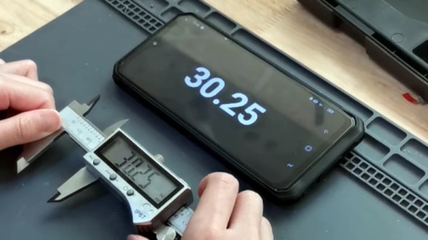
A good instrument stays with its owner for a lifetime, becoming part of their essential trusted toolkit to be consulted as a matter of habit. If you use a caliper to measure dimensions  you’ll know this, and a quick glance at its scale or digital display will be second nature. But if you aren’t fortunate enough to have the eyesight to see the caliper, then it’s off-limits, and that’s something [Naomi Wu] has addressed with her open-source accessible speaking caliper app. It’s an Android app that connects to digital calipers that contain Bluetooth connectivity, and as well as speaking aloud the caliper reading it also displays it in very large text on the device screen. As well as the source link from which you can build the app, it’s available for installation directly from the Google Play Store.

If you’re used to [Naomi] from her video tours of the electronics businesses in her native Shenzhen, her eye-catching wearable projects, or her exploits with an industrial CNC machine in her living room, you might be interested to know that aside from this app she’s been a long-time proponent of open-source in China. She was responsible among other projects for the Sino:bit educational computer board, which holds the distinction for her of having secured the first ever Chinese OSHWA certification.

You can see the caliper app in action below the break.

Continue reading “Digital Caliper Talks For Accessibility, With This App”

Improved Digital Caliper Interfacing, Including 3D Printed Connector

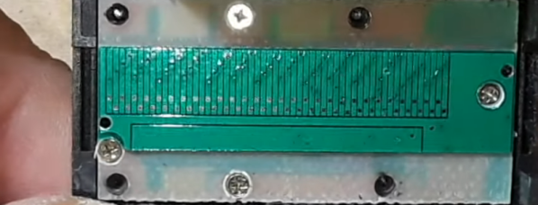
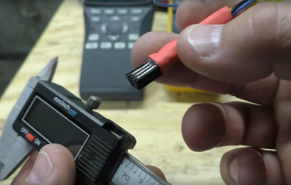
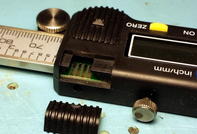
[MakinStuff] wrote in to let us know about a project he did for new and improved interfacing to the ubiquitous cheap Chinese digital calipers. Interfacing to this common caliper model is well-trod ground, but his project puts everything about interfacing and reading the data in one place along with some improvements: a 3D printed connector that makes mating to the pads much more stable and reliable, 3d-printed-plug-for-digital-calipersa simple interface circuit for translating the logic levels, and an interrupt-driven sample Arduino sketch to read the data. Making the sketch interrupt-driven means the Arduino never sits and waits for input from the calipers, making it easier have the Arduino do other meaningful work at the same time, ultimately making it easier to incorporate into other projects.
The connector has spaces to insert bare wires to use as contacts for the exposed pads inside the calipers. Add a little hot glue and heat shrink, and you’ll never have to fiddle with a hacked-together connection again.

This common caliper model has been hacked and re-purposed in interesting ways. We’ve seen them used as a Digital Read Out (DRO) on a lathe as well as being given the ability to wirelessly log their data over Bluetooth.

Continue reading “Improved Digital Caliper Interfacing, Including 3D Printed Connector”

DIY Lathe DRO

Digital Caliper Sacrificed For DRO Project

In general, machining metal on a lathe or mill takes skill and patience as the accuracy of the cuts are important. To make those accurate cuts, it is important to know where the tool is located and how far it moves. For manual machines, the most basic method of determining position is by using graduated dials mounted on the hand cranks. Although these graduated dials can certainly be accurate, they may be difficult to see and they also require the operator to do math in their head on the fly with every full revolution of the dial. Another option would be a digital read out (DRO) which has an encoder mounted to the moving axes of the machine. This setup displays the exact position of the tool on an easy to read numeric display.

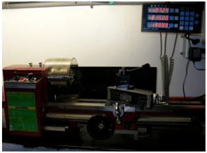
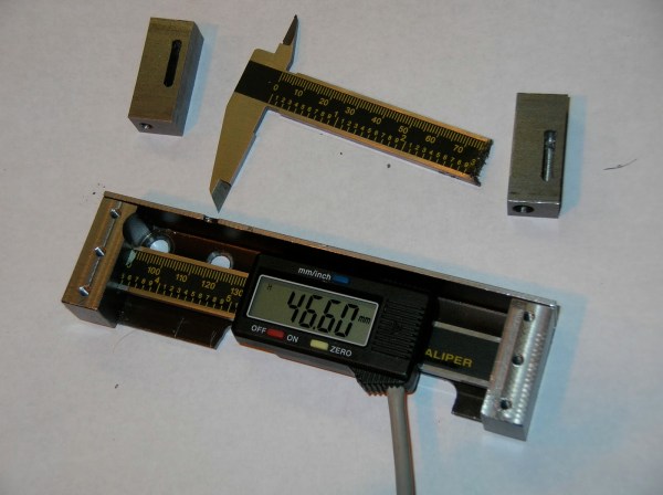
Professional DRO kits for mills and lathes can cost between a few hundred dollars to several thousand dollars.  [Robert] has a lathe, wanted a DRO but didn’t want to shell out serious cash to get it. He built his own for super cheap in an extremely resourceful way…. using a Harbor Freight Digital Caliper. A housing was first fabricated so that the added equipment would not hinder the axis travel of the lathe. The caliper was then cut to length, installed in the housing and the entire assembly was then mounted to the lathe.

DIY Lathe DROIt is totally reasonable to use the stock caliper display to read the positional information, however, even these cheap digital calipers have connections for the encoder output data, which can easily be read by a microcontroller. That means it is super simple to hook these low-cost digital calipers up to a display remotely located in a more convenient position.
 

Three Axis Position Indicator With Digital Calipers

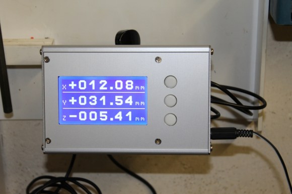
[Malte] just finished a little project for his Wabeco F1200 milling machine: a compact external display for three digital sliding calipers (Translated from German). As you may have already guessed, [Malte] was lucky enough to be able to fit disassembled calipers onto the machine and use them for positioning. Before embarking on this adventure, he noticed that there were similar projects present on the internet, but all of the calipers used had different data interfaces and protocols. The calipers that [Malte] bought have a mini USB connector, even though the interface itself isn’t USB. As he couldn’t find any information on that interface, he turned to his oscilloscope to decode the protocol.

[Malte] then built an AVR-based platform that reads out the three calipers and shows the position data on the dot matrix LCD shown above. The AVR firmware is written in a mixture of Basic and assembler language. The source code, schematics, and other resources can be downloaded from the project’s web page. We are impressed on the professional aspect of the final result.

Continue reading “Three Axis Position Indicator With Digital Calipers”