Syringe with diluted nail polish used to fill into cursive "FuzzyLogic" letters extruded into a surface of a 3D-printed block of plastic, as a demonstration.

Brighten Up Your Prints With This Nail Polish Approach

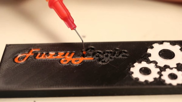
It’s not enough to 3D-print a part – there’s a myriad of things you can do from there! [FuzzyLogic] shows us his approach of adding inlay labels, icons and text to a 3D print, by extruding them into the print and filling the resulting cavity with nail polish! This makes for colorful and useful prints, as opposed to dull single-color parts we typically end up with.

The devil’s in the details, and [FuzzyLogic] has got the details down to a technique. Nail polish has to be diluted with acetone so that it flows well, and a particular combination of syringe and needle will be your friend here. Of course, don’t forget to factor surface tension in – even with well-diluted nail polish, you cannot make the grooves too thin. A bit more acetone on a q-tip helps in case of any happy little accidents, and a coat of clear acrylic spray paint seals the lettering firmly in place. The five-minute video tells you all about these things and a quite few more, like the basics of extruding text and icons in a typical CAD package, and has a bit of bonus footage to those watching until the end.

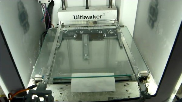
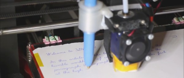
Adding markings to our prints is a lovely finishing touch! If you’re looking for more of that, here’s a custom tool-changing printer with a pen attachment making beautiful custom enclosures for the Pocket Operator.

Continue reading “Brighten Up Your Prints With This Nail Polish Approach”

More LEDs Means Faster Print Times For 3D Printer, But There’s A Catch

[Jan Mrázek] is no stranger at all to home-grown improvements with his Elegoo Mars SLA 3D printer, and there is a lot going on in his experimental multi-LED upgrade which even involved casting his own lens array. In the end it did speed up his prints by a factor of three to four, though he cooked an LCD to failure in the process. Still, it was a fun project done during a COVID-19 lockdown; as usual there is a lot to learn from [Jan]’s experiences but the mod is not something he necessarily recommends people do for themselves.

[Jan] started by wondering whether better print quality and performance could be obtained by improving the printer’s UV light source. The stock printer uses a single large UV LED nestled into a reflector, but [Jan] decided to try making a more precise source of UV, aiming to make the UV rays as parallel as possible.

Custom LED array molded in clear epoxy.

To do this, he took a two-pronged approach. One was to replace the single large UV LED with a 4×7 array of emitters plus heat sink and fans. The other was to make a matching array of custom lenses to get the UV rays as parallel as possible.

Casting one’s own lens array out of clear epoxy was a lot of work and had mixed results, but again, it was a lockdown project and the usual “is-this-really-worth-it” rules were relaxed. In short, casting a single custom lens out of clear epoxy worked shockingly well, but when [Jan] scaled it up to casting a whole 4×7 array of them, results were mixed. Mold deformation and artifacts caused by the areas between individual lenses robbed the end result of much of its promise.

More success was had with the array of UV emitters, which enabled faster curing thanks to higher power, but the heat needs to be managed. The stock emitter of the printer is about 30 W, and [Jan] was running his new array at 240 W. This meant a blazing fast one second exposure time per layer, but the heat generated by the new lighting was higher than anticipated. After only ten hours the LCD failed, probably at least in part due to the heat. [Jan] halved the power of the array down to 120 W and added an extra fan, which appears to have done the trick. Exposure time is two to three seconds per layer, and it’s up to 150 hours of printing without problems.

Again, it’s not a process [Jan] necessarily recommends to others (and he definitely recommends buying lenses if at all possible instead of casting them) but as usual there is a lot to learn from his frank sharing of results, both good and bad. We’ve seen 3D-printed lenses as well as adding WiFi connectivity to one of these hobbyist printers, and it’s great to see the spirit of hacking alive and well when it comes to these devices.

Automatic part remover for 3D printer

Automatically 3D Print Infinite Number Of Parts

We’ve seen 3D printers coming out with infinite build volumes, including some attempts at patenting that may or may not stall their development. One way around the controversy is to do it in a completely different way. [Aad van der Geest]’s solution may not give you the ability to print an infinitely long part, but it will allow you to print an infinite number of the same, or different, parts, at least until your spool runs out.

[Aad]’s solution is to have a blade automatically remove each part from the print bed before going on to the next. For that he put together a rail system that sits on the bed of his Ultimaker 2, but out of the way on the periphery. A servo at one end pulls a blade along the rails, sweeping over the bed and moving any parts on the bed to one end where they fall away. This is all done by a combination of special G-code and a circuit built around a PIC12F629.

One of many things that we think is pretty clever, as well as fun to watch, is that after the part is finished, the extruder moves to the top corner of the printer and presses a micro switch to tell the PIC12F629 to start the part removal process. You can see this in the first video below. The G-code takes over again after a configurable pause.

But [Aad]’s put in more features than just that. As the second video below shows, after the parts have been scraped from the build plate, a pin on the extruder is used to lift and drop the blade a few times to remove small parts that tend to stay on the blade. Also, the extruder is purged between prints by being moved over a small ridge a few times. This of course is also in that special G-code.

How do you produce the special G-code, since obviously it also has to include the parts to print? For that [Aad]’s written a Windows program called gcmerge. It reads a configuration file, which you edit, that contains: a list of files containing the G-code for your parts, how many to print, whether or not you want the extruder to be purged between prints, various extruder temperatures, cooling times, and so on. You can find all this, as well as source for the gcmerge program, packaged up on a hackaday.io page. Incidentally, you can find the PIC12F629 code there too.

Continue reading “Automatically 3D Print Infinite Number Of Parts”

Writing with a 3D printer

Good Penmanship With A 3D Printer

[Chris Mitchell] was going to make his own plotter for doing cursive writing for cards but realized he might be able to use his 3D printer to do the writing instead. But then he couldn’t find any suitable software so he did what you’re supposed to do in this situation, he wrote his own called 3DWriter. He even 3D printed a holder so he could attach a pen to the side of the extruder. When not in use as a plotter he simply retracts the pen tip.

The software is written in C# for Windows and is available on GitHub along with a detailed write-up. He clearly put a lot of thought into what features the software offers. After selecting the font, you type in whatever you want printed and then preview it to make sure it looks good. There’s also a bunch of G-Code settings you can fill in such as bed size, the horizontal and vertical offsets of the pen tip from the extruder tip, drawing speed and so on. There’s even an option to do a dry run with the pen raised so you can make sure it’ll draw on the bed where you expect it to.

The code itself is quite clean and easy to understand. If you’re curious like we were at what information is in the font files and how it’s translated into G-Code then download the source from the GitHub page and have a look. [Chris] settled on a font set called Hershey fonts since they’re primarily stroke based fonts as opposed to outline fonts which are what other programs he’d looked at used.

This makes us think of all those 3D printers with busted extruders we’ve seen collecting dust on hackerspace shelves or simply ones considered obsolete. Using them as a plotter gives them new life — even if just as a fun way to learn about writing code for CNC machines. It makes us wonder what other 2D uses they can be put to… cutting vinyl? laser printing? Ideas anyone?

In any case, have a look at the video below to see it in action as a 2D plotter. As a bonus, you’ll also see line art it drew using an Inkscape plugin.

Continue reading “Good Penmanship With A 3D Printer”

Upgrading A 3D Printer With A Leadscrew

Consumer 3D printers have really opened up the floodgates to personal at home fabrication. Even the cheapest of 3D printers will yield functional parts — however the quality of the print varies quite a lot. One of the biggest downfalls to affordable 3D printers is the cost cutting of crucial parts, like the z-Axis. Almost all consumer 3D printers use standard threaded rod for the z-axis, which should really use a leadscrew instead.

Threaded rod is not designed for accurate positioning — it’s primarily designed to be a fastener. You can have issues with backlash, wobble, and they usually aren’t even perfectly straight — not to mention they gunk up easily with dirt and grime. In other words, you’ll never see a threaded rod on a commercial machine.

Continue reading “Upgrading A 3D Printer With A Leadscrew”