Proper Routing Makes For Many Happy Return Paths

Here’s a question for you: when your PCB has a ground plane layer, where do return signals flow? It seems like a trick question, but as [Kristof Mulier] explains, there’s more to return path routing (alternate link in case you run into a paywall) than just doing a copper pour and calling it a day.

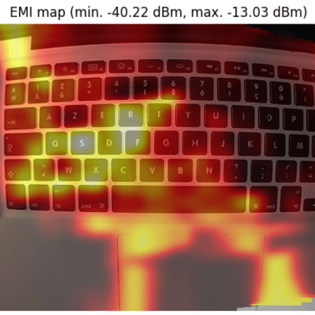
Like so many other things in life, the answer to the above question is “it depends,” and as [Kristof] ably demonstrates in this concise article, the return path for a signal largely depends on its frequency. He begins by explaining current loop areas and how they factor into the tendency for a circuit to both emit and be susceptible to electromagnetic noise. The bigger the loop area, the worse things can get from a noise perspective. At low frequencies, return signals will tend to take the shortest possible path, which can result in large current loop areas if you’re not careful. At higher frequencies, though, signals will tend to follow the path of minimal energy instead, which generally ends up being similar to the signal trace, even if it has a huge ground plane to flow through.

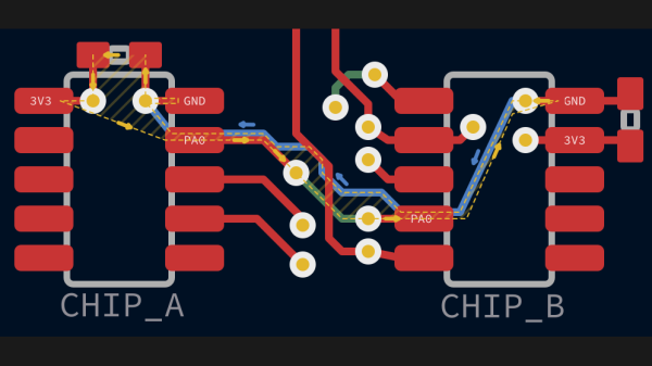
Since high-frequency signals naturally follow a path through the ground plane that minimizes the current loop, that means the problem takes care of itself, right? It would, except that we have a habit of putting all kinds of gaps in the way, from ground plane vias to isolation slots. [Kristof] argues that this can result in return paths that wiggle around these features, increasing the current loop area to the point where problems creep in. His solution? Route all your signal return paths. Even if you know that the return traces are going to get incorporated into a pour, the act of intentionally routing them will help minimize the current loop area. It’s brilliantly counterintuitive.

This is the first time we’ve seen the topic of high-frequency return paths tackled. This succinct demonstration shows exactly how return path obstructions can cause unexpected results.

Thanks to [Marius Heier] for the tip.

Simple Probe Sniffs Out EMI

Unable to account for the strange glitches he was seeing on his DIY CNC router, [Daniël Van Den Berg]  wondered if his electronics might be suffering from some form of electromagnetic interference (EMI). So he did what any good hacker would do, and rummaged through the parts bin to build an impromptu EMI detector.

[Daniël] is quick to point out that he’s not an electrical engineer, and makes no guarantees about the accuracy of his tossed together gadget. But it does seem to work well enough in his testing that he’s able to identify particularly “noisy” electronic components, so it’s probably worth putting one together just to hear what your hardware is pumping into the environment.

The hardware here is very simple, [Daniël] just attached a coil of solid copper wire to one of the analog pins on an Arduino Nano with a resistor, and hung a speaker off of one of the digital pins. From there, it just took a few lines of code to read the voltage in the coil and convert that into a tone for the speaker. The basic idea is that a strong alternating magnetic field will set up voltage fluctuations in the coil large enough for the Arduino’s ADC to read.

If you’re looking for a bit more insight into what kind of interference your electronic creations might be putting out, [Alex Whittimore] gave a fantastic presentation during the 2020 Hackaday Remoticon about performing RF debugging using a cheap RTL-SDR dongle.

A Practical Look At Chokes For EMI Control

Radio frequency electronics can seem like a black art even to those who intentionally delve into the field. But woe betide the poor soul who only incidentally has to deal with it, such as when seeking to minimize electromagnetic interference. This primer on how RF chokes work to reduce EMI is a great way to get explain the theory from a practical, results-oriented standpoint.

As a hobby machinist and builder of machine tools, [James Clough] has come across plenty of cases where EMI has reared its ugly head. Variable frequency drives are one place where EMI can cause problems, and chokes on the motor phase outputs are generally prescribed. He used an expensive choke marketed as specific for VFD applications on one of his machines, but wondered if a cheap ferrite core would do the job just as well, and set to find out.

A sweep of some ferrite cores with a borrowed vector network analyzer proved unsatisfying, so [James] set up a simple experiment with a function generator and an oscilloscope. His demo shows how the impedance of a choke increases with the frequency of the test signal, which is exactly the behavior that you’d want in a VFD – pass the relatively low-frequency phase signals while blocking the high-frequency EMI. For good measure, he throws a capacitor in parallel to the choke and shows how much better a low-pass filter that makes.

We love demos like this that don’t just scratch an intellectual itch but also have a practical goal. [James] not only showed that (at least in some cases) a $13 ferrite can do the same job as a $130 VFD choke, but he showed how they work. It’s basic stuff, but it’s what you need to know to move on to more advanced RF filter designs.

Continue reading “A Practical Look At Chokes For EMI Control”

The RFI Hunter: Looking For Noise In All The Wrong Places

Next time you get a new device and excitedly unwrap its little poly-wrapped power supply, remember this: for every switch-mode power supply you plug in, an amateur radio operator sheds a tear. A noisy, broadband, harmonic-laden tear.

The degree to which this fact disturbs you very much depends upon which side of the mic you’re on, but radio-frequency interference, or RFI, is something we should all at least be aware of. [Josh (KI6NAZ)] is keenly aware of RFI in his ham shack, but rather than curse the ever-rising noise floor he’s come up with some helpful tips for hunting down and eliminating it – or at least reducing its impact.

Attacking the problem begins with locating the sources of RFI, for which [Josh] used the classic “one-circuit-at-a-time” approach – kill every breaker in the panel and monitor the noise floor while flipping each breaker back on. This should at least give you a rough idea of where the offending devices are in your house. From there, [Josh] used a small shortwave receiver to locate problem areas, like the refrigerator, the clothes dryer, and his shack PC. The family flat-screen TV proved to be quite noisy too. Remediation techniques include wrapping every power cord and cable around toroids or clamping ferrite cores around them, both on the offending devices and in the shack. He even went so far as to add a line filter to the dryer to clamp down on its unwanted interference.

Judging by his waterfall displays, [Josh]’s efforts paid off, bringing his noise floor down from S5 to S1 or so. It’s too bad he had to take matters into his own hands – it’s not like the FCC and other spectrum watchdogs don’t know there’s a problem, after all.

Continue reading “The RFI Hunter: Looking For Noise In All The Wrong Places”

Camera Sees Electromagnetic Interference Using An SDR And Machine Vision

It’s one thing to know that your device is leaking electromagnetic interference (EMI), but if you really want to solve the problem, it might be helpful to know where the emissions are coming from. This heat-mapping EMI probe will answer that question, with style. It uses a webcam to record an EMI probe and the overlay a heat map of the interference on the image itself.

Regular readers will note that the hardware end of [Charles Grassin]’s EMI mapper bears a strong resemblance to the EMC probe made from semi-rigid coax we featured recently. Built as a cheap DIY substitute for an expensive off-the-shelf probe set for electromagnetic testing, the probe was super simple: just a semi-rigid coax jumper with one SMA plug lopped off and the raw end looped back and soldered. Connected to an SDR dongle, the probe proved useful for tracking down noisy circuits.

[Charles]’ project takes that a step further by adding a camera that looks down upon the device under test. OpenCV is used to track the probe, which is moved over the DUT manually with the help of an augmented reality display that helps track coverage, with a Python script recording its position and the RF power measurements. The video below shows the capture process and what the data looks like when reassembled as an overlay on top of the device.

Even if EMC testing isn’t your thing, this one seems like a lot of fun for the curious. [Charles] has kindly made the sources available on GitHub, so this is a great project to just knock out quickly and start mapping.

Continue reading “Camera Sees Electromagnetic Interference Using An SDR And Machine Vision”

Build Your Own EMI Probes

[Gerald Musy] wanted to investigate the source of electromagnetic interference (EMI) in his switching power supply design. Stymied by the high cost of EMI probes, he decided to build his own. Lucky for us, he wrote up his results of experimenting with four different designs.

The probes include an unshielded loop, a shielded loop, a ferrite core probe, and an electric field probe. None of these are especially complex to build–the ferrite core one is probably the most involved–you can see from the scope traces that the different probes pick up different information.

Continue reading “Build Your Own EMI Probes”

Listening To Electromagnetic Interference With A RTLSDR Dongle

Being curious by nature, [Marios] decided to see what kind of radio-frequency emissions may be generated by an Arduino connected to a simple breadboard wire, and more importantly try to pick them up using a RTLSDR dongle. Electromagnetic interferences are disturbances that affect electrical circuits due to either electromagnetic induction or electromagnetic radiation. Before going into the market, all electrical devices are thoroughly checked for unwanted electromagnetic emissions so they usually aren’t obvious suspects when such problems arise.

Using the Arduino embedded PWM controller in fast PWM mode and by manipulating the duty cycle, he actually managed to create a primitive form of amplitude modulation and was able to transfer a very simple audible signal at several frequencies up to 1.75GHz. Embedded after the break here is video of the system at work.

As a side note, did you know that during the solar storm of 1859 the EMI were so strong that the telegraph operators received several shocks? Pipelines maintenance systems also have to be aware of such events, that can lead sensors to provide inaccurate results.

Continue reading “Listening To Electromagnetic Interference With A RTLSDR Dongle”