A Receive Antenna Switcher With An Espressif Brain

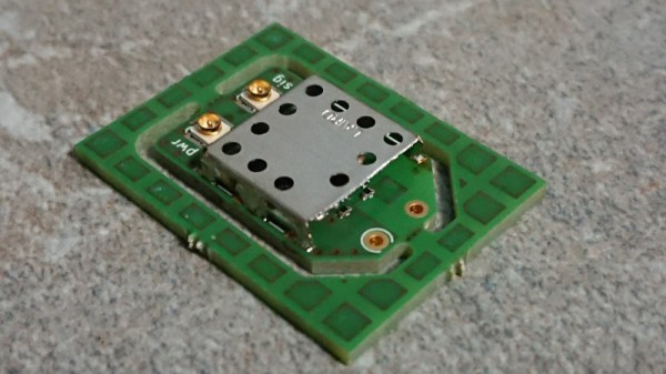
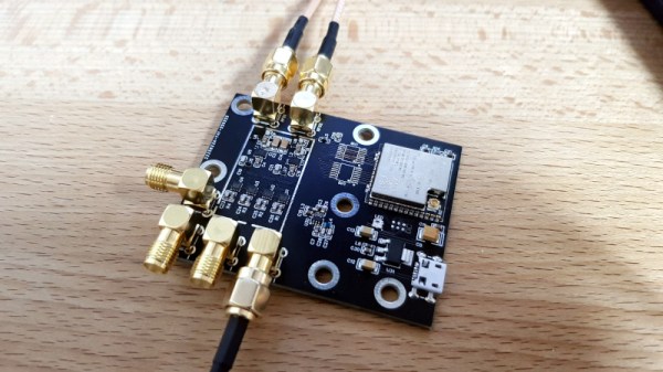
It’s not uncommon for a radio enthusiast to have multiple antennas for the same radio, so as you might expect it’s also entirely usual to have a bunch of coaxial cables dangling down for fumbling around the back of the rig to swap over.  If that describes your radio experience than you might be interested in the antenna switcher built by [g3gg0], which uses solid-state RF switches controlled by an ESP32 module.

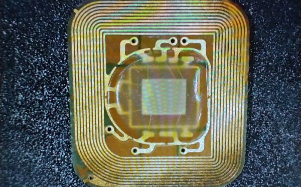
At its heart is the MXD8625C RF switch, a tiny device designed for cellular phone applications that delivers only a fraction of a dB insertion loss and somehow negates the need for any blocking capacitors. It’s controlled by a GPIO line, and he’s hooked up a brace of them to allow the distribution of three antennas to a couple of radios with the handy option of switching in a preamplifier if required. Of even more interest we note that the device is suitable for transmitter switching too, with a maximum 36.5 dBm throughput that we calculate to be about 4.5 W. This board is fairly obviously for receive use, but perhaps the chip is of interest to anyone considering a transceiver project. Meanwhile the software is a relatively simple web-based control linking on-screen controls to GPIOs.

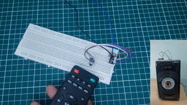
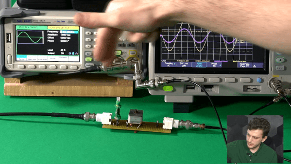
If you are interested in solid state RF switches, it’s always worth remembering that at lower frequencies they can be very simple indeed.

A FET Oscilloscope Probe For Higher Frequencies

It’s a problem that has dogged electronic engineers since the first electrons were coaxed along a wire: that measuring instruments can themselves disrupt the operation of a circuit. Older multimeters for example had impedances low enough to pull resistor values, thus our multimeters today have high-impedance FET inputs. [Christoph] faced it with his oscilloscope probe, its input capacitance was high enough to put unacceptable load on a crystal oscillator and stop it oscillating. He thus built a FET input probe for higher RF frequencies, and its construction is an accessible view of wideband RF instrumentation design.

The circuit is a very simple one using a dual-gate FET, but the interest comes in the PCB and screening can design to ensure good RF performance. Off-the-shelf cans have four sides, so to accommodate the circuit one wall of the can had to be removed. The end result is a tiny PCB with miniature co-ax connectors for power and signal, which when characterised was found to have a 1.3 GHz bandwidth and a very low input capacitance.

If the language of RF design is foreign to you, may we recommend [Michael Ossmann]’s talk at a Superconference a few years ago.

IR Remote Transforms To RF

Most consumer remote controls operate using infrared light. This works well assuming the piece of equipment has a line of sight to the remote. But if you have, say a receiver in a cabinet or closet, the IR remote signal can’t reach the sensor. Some equipment has remote receivers that you can leave poking out, but it is still not very handy. That’s why some equipment now uses RF remotes. [Xtropie] used a pair of inexpensive 433 MHz RF modules to convert an IR system to RF. You can see a short video about the project below.

We might have been tempted to simply put an IR LED on the receiver so it could feed IR into the device sensor, but [Xtropie] took a different approach. He found the IR sensor and tied the RF receiver directly into its output. It seems to work, but we probably would have removed the IR sensor to make sure there were no conflicts.

Continue reading “IR Remote Transforms To RF”

Impedance Matching Revisited

If you are an old hand at RF design, you probably have a good handle on matching impedance. However, if you are just getting started with RF, [FesZ Electronic]’s latest video series on lossless impedance matching is well worth watching.

Matching is important for several reasons. Maximum power transfer occurs when the source and load impedance match. Also, at RF, mismatched impedance can cause reflections which, again, robs you of useful power. The video covers some math and then moves on to LTSpice to simulate a test circuit. But the part you are really waiting for — the practical circuits — is about 15 minutes in. Since the values you need are often oddball, [FesZ] makes his own adjustable inductors and uses a trimmer capacitor to adjust the actual capacitance value.

This is a big topic, but the first video is a great introduction blending theory, simulation, and hands-on. A great way to get started with a very fundamental RF design skill.

We’ve worked on explaining all this before if you want a second take on it. If you want to understand why mismatched impedance leads to less power delivery, we’ve done that, too.

Continue reading “Impedance Matching Revisited”

NFC Performance: It’s All In The Antenna

NFC tags are a frequent target for experimentation, whether simply by using an app on a mobile phone to interrogate or write to tags, by incorporating them in projects by means of an off-the-shelf module, or by designing a project using them from scratch. Yet they’re not always easy to get right, and can often give disappointing results. This article will attempt to demystify what is probably the most likely avenue for an NFC project to have poor performance, the pickup coil antenna in the reader itself.

A selection of the NFC tags on my desk

The tags contain chips that are energised through the RF field that provides enough power for them to start up, at which point they can communicate with a host computer for whatever their purpose is.

“NFC” stands for “Near Field Communication”, in which data can be exchanged between physically proximate devices without their being physically connected.  Both reader and tag achieve this through an antenna, which takes the form of a flat coil and a capacitor that together make a resonant tuned circuit. The reader sends out pulses of RF which is maintained once an answer is received from a card, and thus communication can be established until the card is out of the reader’s range. Continue reading “NFC Performance: It’s All In The Antenna”

Ethernet Cable Turned Into Antenna To Exploit Air-Gapped Computers

Good news, everyone! Security researcher [Mordechai Guri] has given us yet another reason to look askance at our computers and wonder who might be sniffing in our private doings.

This time, your suspicious gaze will settle on the lowly Ethernet cable, which he has used to exfiltrate data across an air gap. The exploit requires almost nothing in the way of fancy hardware — he used both an RTL-SDR dongle and a HackRF to receive the exfiltrated data, and didn’t exactly splurge on the receiving antenna, which was just a random chunk of wire. The attack, dubbed “LANtenna”, does require some software running on the target machine, which modulates the desired data and transmits it over the Ethernet cable using one of two methods: by toggling the speed of the network connection, or by sending raw UDP packets. Either way, an RF signal is radiated by the Ethernet cable, which was easily received and decoded over a distance of at least two meters. The bit rate is low — only a few bits per second — but that may be all a malicious actor needs to achieve their goal.

To be sure, this exploit is quite contrived, and fairly optimized for demonstration purposes. But it’s a pretty effective demonstration, but along with the previously demonstrated hard drive activity lights, power supply fans, and even networked security cameras, it adds another seemingly innocuous element to the list of potential vectors for side-channel attacks.

[via The Register]

Is A Diode A Switch?

Many hardware people around these parts will be familiar with devices used as switches, using at least three-terminals to effect this, an input, an output and a gate. Typical devices that spring to mind are bipolar transistors, triacs and and ye olde triode valve. Can you use a diode to switch a signal even if it has only two terminals? Of course you can, and it’s a tried and trusted technique very common in test equipment and circuits that handle RF signals. (Video, embedded below.)

The trick is that diodes block current in one direction but allow it to flow in the other, denoted by the deliberately obvious symbol. So your DC signals can’t swim upstream, but the same isn’t true for AC. Signals can be passed “the wrong way” through a diode by inducing small fluctuations in the current. Put another way, if you bias the diode into conduction, changes in the downstream voltage level result in changes in the current flowing through the diode, and the (smaller) AC signal gets through. But if you take away the bias, by turning off the DC bias voltage source, the diode switches back to non-conducting, blocking the signal. And that makes a diode a DC controlled switch for AC signals.

While [IMSAI Guy] demonstrates this with a signal diode, as he explains, one would typically use a PIN diode, which has an extra intrinsic (undoped) region between the P and the N, allowing the device to fully turn off, reducing leakage significantly.

Of course, we’ve covered diodes many times from different angles, there is always something to learn. Checkout how high voltage diodes are constructed, diodes detecting ionising radiation, and finally this great series about our new favourite two-terminal device.

See, the humble diode can be fun after all!

Continue reading “Is A Diode A Switch?”