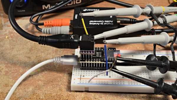
The average punter shunts audio around with analog 3.5 mm cables, RCA jacks, or Bluetooth on a regular basis. A useful standard that hasn’t really bothered most of us is S/PDIF, standing for Sony/Phillips Digital Interface. It’s a useful way to pump digital audio around over copper cables or optic fiber. [Andrew Jeddeloh] got curious about the standard after contemplating some long cable runs in his home, and decided to try decoding it.
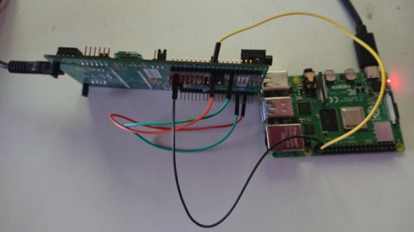
The target for [Andrew]’s development efforts was the STM32L476 Discovery, which had no SPDIF decoding hardware on board. Instead, [Andrew] tinkered with the peripherals he had to see what would work. In the end, a cavalcade of internal timers were daisy chained to allow the microcontroller to recover a clock from the self-clocked S/PDIF signal. This was then used to generate a clock to sync up the onboard SPI hardware to actually read in the 16-bit PCM data from the S/PDIF signal.
[Andrew]’s original broader plan was to pipe the S/PDIF data to the onboard I2S DAC, though he struggled manipulating the remaining resources on the STM chip to do so successfully. Anyone wishing to have a crack can take a look at [Andrew]’s code over on GitHub. If completed, the STM32L476 would become a useful analog endpoint for S/PDIF streams, allowing you to pump tunes digitally over long distances without signal degradation. If you know the key to getting it done, sound off in the comments! Alternatively, if you need to get up and running more quickly, the Teensy platform has you covered!
 On the hardware side, [Paul] has