EMC Tutorial Puts You In The Loop

A student once asked his lab instructor why his amplifier was oscillating. After looking at it and noting the wild construction, the instructor remarked, “A better question would be why shouldn’t it oscillate?” The truth of it is, our circuits generate noise and especially if they are oscillating anyway. Distortion and nonlinearities generate harmonics and other component imperfections also contribute.

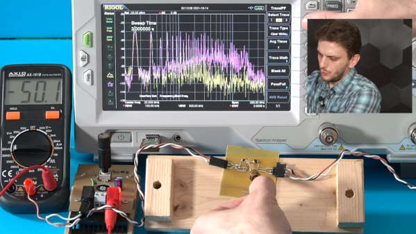
[FesZ Electronics] has a great video series about noise in switching power supplies and the latest talks about the hot loop. If you want to improve the noise performance of your next design, these videos are well worth watching. You can see the hot loop video below.

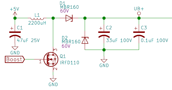
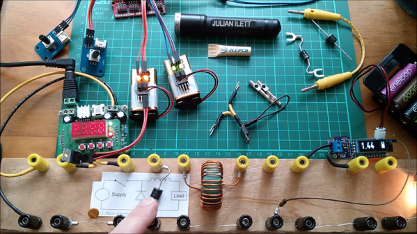
We really liked the homebrew noise probes. In addition to real-world probing. The video also observes circuit operation under simulation. Even if you don’t care about noise performance, there’s a lot of good information about basic switching power supply design here.

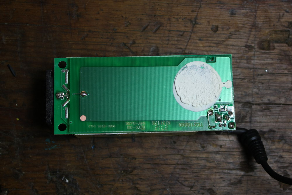
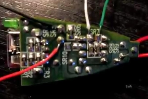
You can see the difference in a PCB that has a small hot loop versus a very small hot loop. Something to think about next time you are laying out a power supply board.

If you want to dive deeper into noise simulation, we have a good read on that for you. Or ditch simulation, and make your own cheap probe with an SDR dongle.

Continue reading “EMC Tutorial Puts You In The Loop”

Tiny Cube Hosts A Hearty Tube

Tiny PCBAs and glowy VFD tubes are like catnip to a Hackaday writer, so when we saw [hamster]’s TubeCube tube segment driver we had to dig in to learn more. We won’t bury the lede here; let’s enjoy a video of glowing tubes before we go further:

The TubeCube is built to fit the MiniBadge badge addon standard, which is primarily used to host modules on the SAINTCON conference badge. A single TubeCube hosts a VFD tube, hardware to provide a 70 V supply, and a microcontroller for communication and control. Each TubeCube is designed to accept ASCII characters via UART to display on it’s display, but they can also be chained together for even more excitement. We’re not sure how [hamster] would be able to physically wear the beast in the video above, but if he can find a way, they all work together. If you’re interested in seeing the dead simple UART communication scheme take a look at this file.

We think it’s also worth pointing about the high voltage supply. To the software or mechanically minded among us it’s easy to get trapped thinking about switching power supplies as a magical construct which can only be built using all-in-one control ICs. But [hamster]’s supply is a great reminder that a switching supply, even a high voltage one, isn’t as complex as all that. His design (which he says was cribbed from Adafruit’s lovely Ice Tube Clock) is essentially composed of the standard primitives. A big low voltage capacitor C1 to source the burst of energy which will be boosted, the necessary inductor/high voltage cap C2 which ends up at the target voltage, and a smoothing cap C3 to make the output a little nicer. It’s controlled by the microcontroller toggling Q1 to control the current flow through L1. The side effect is that by controlling the PWM frequency [hamster] can vary the brightness of the tubes.

Right now it looks like the repository has a schematic and sources, which should be enough to build a small tube driver of your own. If you can’t get enough TubeCubes, there’s one more video (of a single module) after the break.

Continue reading “Tiny Cube Hosts A Hearty Tube”

Circuit VR: An (Almost) Practical Buck Converter

In the last installment of Circuit VR, we walked around a simplified buck converter. The main simplification was using a constant PWM signal. The result is that the output voltage is a fixed fraction of the input voltage. For a regulator, the pulse width will need to depend on the output voltage so that any changes in the output are self-correcting. So this time, we’ll make a regulator, although we’ll still use a few Spice elements you’d have to replace in a practical design. In particular, we’ll assume you can generate a triangle wave, which is easy enough, and produce a stable 2.5 V reference.

The idea is to take a voltage reference and compare it to the output. We’ll think of the difference between the two as an error voltage, and use a comparator combined with a triangle wave generator to produce a PWM signal that is proportional to the error, and thus works to hold the output voltage constant.

Continue reading “Circuit VR: An (Almost) Practical Buck Converter”

Circuit VR: Simple Buck Converters

The first thing I ever built without a kit was a 5 V regulated power supply using the old LM309K. That’s a classic linear regulator like a 7805. While they are simple, they waste a lot of energy as heat, especially if the input voltage goes higher. While there are still applications where linear regulators make sense, they are increasingly being replaced by switching power supplies that are much more efficient. How do switchers work? Well, you buy a switching power supply IC, add an inductor and you are done. Class dismissed. Oh wait… while that might be the best way to do it from a cost perspective, you don’t really learn a lot that way.

In this installment of Circuit VR, we’ll look at a simple buck converter — that is a switching regulator that takes a higher voltage and produces a lower voltage. The first one won’t actually regulate, mind you, but we’ll add that in a future installment. As usual for Circuit VR, we’ll be simulating the designs using LT Spice.

Interestingly, LT Spice is made to design power supplies so it has a lot of Linear Technology parts in its library just for that purpose. However, we aren’t going to use anything more sophisticated than an op amp. For the first pass, we won’t even be using those.

Continue reading “Circuit VR: Simple Buck Converters”

Buck Converter Efficiency

We always appreciate when someone takes the time to build something and then demonstrates what different design choices impact using the real hardware. Sure, you can work out the math and do simulations, but there’s something about having real hardware that makes it tangible. [Julian Ilett] recently posted two videos that fit this description. He built a buck converter and made measurements about its efficiency using different configurations.

The test setup is simple. He monitors the drive PWM with a scope and has power meters on the input and output. That makes it easy to measure the efficiency since it is just the ratio of the power output to input. You can see the two videos, below.

Continue reading “Buck Converter Efficiency”

Sparkfun Tears Apart Power Supplies

We love a good tear-down, and last week’s “Enginursday” at Sparkfun satisfied our desire to see the insides of AC-DC switching power supplies, accompanied by knowledgeable commentary. [MTaylor] walks us through how the basic circuit works and then points out why various other elaborations are made, and how corners are sometimes cut, in a few power supplies that he’s taken apart.

lishin_bottomshieldedWhat struck us in the comparison was that some of the power supplies were very minimal designs, while others had “features” that were obviously added after the fact. For instance, the Li Shin supply (about half-way down the page) has an extra circuit board tacked on to the bottom of the real circuit board to act as EM shielding.

Rather than declare this a dodgy hack, as we would have, [MTaylor] declares it to be “Good News!” because it means that they’ve probably run an emissions test, failed it, and then added this bit on to make it pass. This is of course in contrast to the other makers who’ve probably never even considered emissions testing. Sigh.

If you’re interested in seeing more inner bits of power bricks, Sparkfun forum reader [sgrace] passed along this field guide to various power supplies, which is also worth a look. And if you’re interested in building yourself the ultimate bench power supply, look no further than this Hackaday.io project by [The Big One].

Crack Open A USB Car Charger To Make It A Variable DC-DC Converter

[Boolean90] hacked a cheap USB car charger into a variable power supply. His proof of concept is to use this as a variable-speed motor controller. The best part is that nothing is being abused, the regulator inside is still running within manufacturer’s spec.

While we’ve seen similar hacks before, [Boolean90]s video is pretty cool and provides a nice insight into the components used in these cheap devices. Rather than a linear regulator, which would dissipate too much heat the device uses a common jelybean MC34063A (PDF) switching DC-DC converter which costs about 10 cents on eBay (about two dollars for twenty, shipped). Here it’s used to step the car batteries 12 volts down to 5, but can also be used in step-up and inverting configurations.

Like all switching buck converters the MC34063A uses a PWM (pulse width modulated) signal to drive an inductor and capacitor, which effectively form an LC filter. By controlling the pulse width, the output voltage can be regulated. [Afrotechmods] has a great tutorial on the basic principle. The regulation is controlled by feedback resistors. [Boolean90] simply added a variable resistor to allow the output voltage to be controlled.

Neat hack [Boolean90]! Continue reading “Crack Open A USB Car Charger To Make It A Variable DC-DC Converter”