Puncture Resistant Bike Tires From Old Seatbelts

puncture_resistant_bike_tires

[Nicolás] often rides his bike in the city, and on more than one occasion has ended up with a flat tire. A flat tire might not sound like a big deal, but imagine if you are a few miles from your destination and running late – now your day has gone from bad to worse.

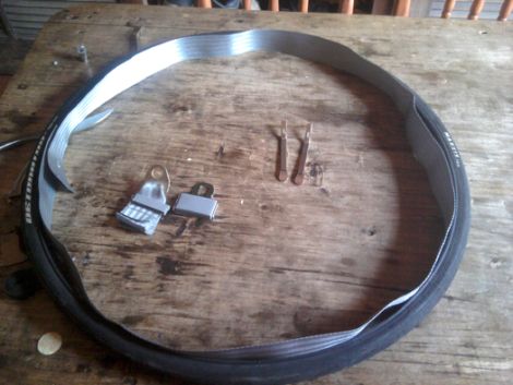
He was contemplating how he might protect his bike’s tires from being punctured by glass and other debris, when he came across some old car seat belts that used to serve as straps for various messenger bags. He pulled the tires off his bike and after removing the inner tubes, he unrolled the seat belts inside the wheels. The belts were cut to size, then the tubes were reinserted into the wheels and inflated as normal.

He hasn’t run into any glass shards just yet, but [Nicolás] is betting that the reinforced nylon mesh of the seat belts will keep his tubes safe whenever he does.

[via Make]

24 Cellphone Buttons Controlled With 6 Microcontroller Pins

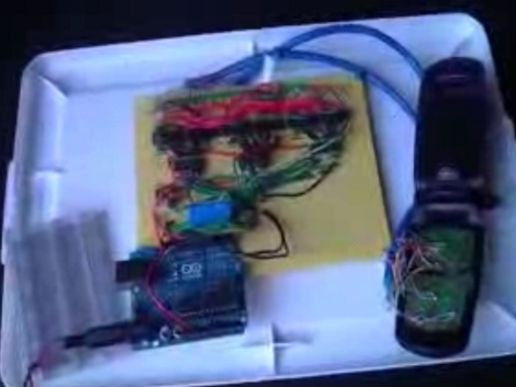
[J8g8j] has been playing around with an old cellphone. He wanted to control it using a microcontroller but since there’s 24 buttons he wasn’t thrilled about hooking up a couple dozen relays to do the switching. Instead, he managed to control all 24-buttons using just 6-pins of a microcontroller.

The proof-of-concept video that he posted on his site shows the phone responding to an arbitrary string of button presses. [J8g8j] spent the majority of his time reverse engineering how the phone’s keypad is wired. Once he figured out the rows and columns of the key matrix he soldered wires to access each of them. This turns out to be 14 connections. To these, he wired up a set of opto-isolators to handle the switching. These are in turn controlled by a set of three 74HC138A 3-8 bit decoders. what’s left are six input pins that leave plenty of room for him to hook up other items to the Arduino serving as the microcontroller.

Building DIY BlinkM Clones

ghetto_pixels

If you are planning on using more than a handful of BlinkMs in a project, you will likely find that their $15 price tag quickly adds up. Instructables user [jimthree] found himself in that position and opted to create his own homebrew version of a BlinkM instead. He calls his creations “Ghetto Pixels”, and while they might not look as professional as the real thing, they get the job done just the same.

He bought a batch of RGB LEDs online for under a dollar apiece, pairing them with ATTiny45s that he scored for about $1.50 each. [imthree] popped his uCs into a programmer, flashing them with an open-source BlinkM firmware clone called CYZ_RGB. He then prototyped his circuit on some breadboard, adding the appropriate resistors to the mix before testing out the LEDs. When he was confident everything was working correctly, he assembled Ghetto Pixels deadbug-style.

When everything was said and done, they came together in a pretty compact package comparable to that of the BlinkM. As you can see in the video below, they work great too!

Continue reading “Building DIY BlinkM Clones”

Automated Scanning For A Pile Of Documents

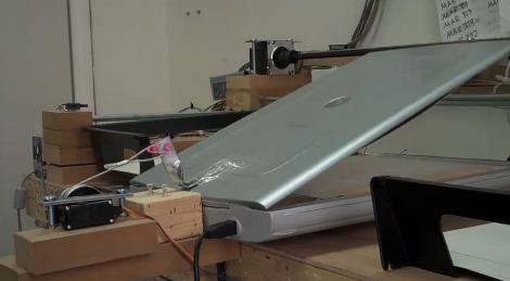
The Gado project is part of the Johns Hopkins University Center for African Studies. It has been tasked with archiving documents having to do with the East Baltimore Oral Histories Project. In short, they’ve got a pile of old pictures and documents that they want digitized but are not easily run through a page-fed scanner because they are fragile and not standard sizes. The rig seen above is an automated scanner which picks up a document from the black bin on the left, places it on the flat-bed scanner seen in the middle, and moves it to the black bin on the right once it has been scanned. It’s not fast, but it’s a cheap build (great if you’ve got a tight budgt) and it seems to work.

The machine is basically a three-axis CNC assembly. Above you can see one motor which lifts the lid of the scanner. You can’t see the document gripper in this image, but check the video after the break which shows the machine in action. A vacuum powered suction cup moves on a gantry (y-axis) but is also able to adjust its height (z-axis) and distance perpendicular to the gantry (x-axis) in order to grab one page at a time.

The pictures on the build log have captions to give you an idea of how this was built. We didn’t see any info about post-processing but let’s hope they have an auto-crop and auto-deskew filter in place to really make this automatic.

Continue reading “Automated Scanning For A Pile Of Documents”

Build A Standalone BASIC Interpreter

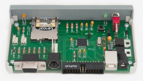
Here’s a photo of the circuit board for the Maximite, a BASIC interpreter that [Geoff] built. The design idea was sparked when he was exploring the possibilities of the PIC32 family of chips. [Geoff] wanted to write about the hardware for a magazine article but needed an actual product to really show it off.

The design can utilize one of two microprocessors, a PIC 32MX795F512H or 32MX695F512H. The 32-bit chip has more than enough power to emulate BASIC, and even allows for floating point calculations. It’s VGA compatible and has a jack for a standard PS/2 keyboard, which makes it a standalone device. You can store programs on an SD card, or it can be interfaced with a computer via the USB-B port that you see next to the power jack. The microprocessor is a surface mount chip, but the rest of the components are through-hole, making this an easy kit to assemble. But if you’re not afraid to etch your own 2-layered PCBs there is board artwork available in [Geoff’s] download package.

[Thanks Bill]

Reworking Ball Grid Array Circuit Board Components At Home

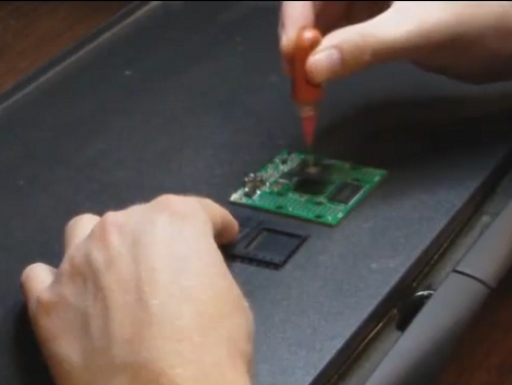
[Jack Gassett] is developing a new breakout board for an FPGA. The chip comes in a ball grid array (BGA) package which is notoriously difficult to solder reliably. Since he’s still in development, the test boards are being assembled in his basement. Of the first lot of four boards, only one is functional. So he’s setting out to rework the bad boards and we came along for the ride.

To reflow the surface mount components he picked up a cheap pancake griddle. The first thing [Jack] does is to heat up the board for about two minutes, then pluck off the FPGA and the FTDI chips using a vacuum tweezers. Next, the board gets a good cleaning with the help of a flux pen, some solder wick, and a regular soldering iron. Once clean, he hits the pads with solder paste from a syringe and begins the soldering process. BGA packages and the solder paste itself usually have manufacturer recommended time and temperature guidelines. [Jack] is following these profiles using the griddle’s temperature controller knob and the timer on an Android phone. In the video after the break you can see that he adjusts the timing based on gut reaction to what is going on with the solder. After cleaning up some solder bridges on the FTDI chip he tested it again and it works!

Continue reading “Reworking Ball Grid Array Circuit Board Components At Home”

Converting A Roomba Into A Mars Rover

When we first heard of [Dino]’s all-terrain Roomba, we hoped the ‘stair-climbing Roomba’ problem had finally been solved, but the final build turned out much cooler.

A year ago, [Dino] built a small robot based on a rocker-bogie suspension. This suspension system has been used on every Mars rover, including the huge Mars Science Labratory scheduled to land on Mars next year. [Dino] beefed up the suspension from the previous version and changed the wheels and center of gravity. Now, the little Roomba rover seems quite capable of climbing over objects as tall as itself.

The control of the rover is similar to other Roomba hacks we’ve seen – just tapping a few transistors. [Dino] is using a Seeduino and an ultrasonic sensor to avoid collisions. [Dino] says that he’s thinking about pivoting each wheel independently to get around the skid-steering, but maybe an omnidirectional wheel would be better suited.

Check out the video after the break for a demo of the Roomba rover traversing the treacherous boulder strewn terrain in [Dino]’s garage.

Continue reading “Converting A Roomba Into A Mars Rover”