Baking Pan Tube Amp Sounds Better Than You’d Expect

baking_pan_tube_amp

A few years back, [Gio] decided to try his hand at building a couple of tube amplifiers.

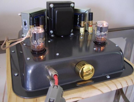
The first amp was more of an experiment to see how well a DIY single-ended tube amp would sound. The amp is based off the 6T9 design created by Spare Time Gizmos, and incorporates a pair of 6T9 vacuum tubes, hence the name.  He wired things up in an afternoon, then got busy drilling holes in a baking pan, where he mounted the amp. Bear with us for a second, it’s not as bad as it sounds. The amp actually looks pretty good mounted in the dark black steel, and this sort of enclosure is far cheaper than most DIY amp enclosures. He says that he was sure to be extra careful in isolating all of the electronic components from the metal chassis.

The second amp was built to test the performance differences between Pentode-mode and Ultra-Linear mode configurations. While both amps share a substantial amount of the same components, his UL amp benefits from slightly better capacitors and an uprated power supply, not to mention a more conventional case.

Both amps sound great, according to [Gio], but should be paired with efficient speakers for the best experience. He does note that the ultra-linear amp is the better choice, mounting options aside.

[Thanks, Philippe]

[via RetroThing]

AVR HVSP On A Tiny Breadboard

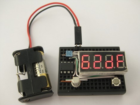
AVR chips are convenient because you can program them in circuit at their operating voltage. That is, unless you screw up the fuse settings and they’ll no longer listen to an In System Programmer. If you find yourself facing this problem, just build this circuit on a breadboard and ‘unbrick’ by holding down the button.

The circuit seen above is a High Voltage Serial Programmer. This is one of two high voltage protocols used by AVR chips; HVSP is for chips that don’t have enough pins to use High Voltage Parallel Programming. This rendition uses a 12V power source, which is the level necessary for the high voltage method. A 7805 linear regulator joins the mix to provide operational voltage, along with one transistor, an ATtiny2313 to control the circuit, a four-digit 7-segment display for feedback, and one button for control.

Watch the video after the break to see an ATtiny13 programmed to disable the reset pin using a breadboarded programmer. That chip is then easily rescued, having been automatically recognized by using its device signature.

Continue reading “AVR HVSP On A Tiny Breadboard”

Alternate Keyboard Layouts – For Geekiness And Other Reasons

[BiOzZ] wanted to try a different keyboard layout than the ubiquitous Qwerty, so he grabbed an old keyboard and converted it to the Dvorak setup. This was accomplished by first popping off all of the keys from the black keyboard seen above, and boy did he find a mess underneath. It was nothing that a trip through the dishwasher (for the case only) wouldn’t fix, and the next step was to replace the keys in a different order. He found that a couple of them wouldn’t just go back in a different place, but had to be rotated 90 degrees to fit. Not a huge problem, you can see that he overcame the visual speedbump of letters facing the wrong way by adding his own letter labels. From there he walks us through the process of getting Windows to switch to the Dvorak layout.

I went through a similar process at the end of last year. I was experiencing a lot of pain in my hands from my prolific feature writing here at Hackaday so I chose to try out the Colemak keyboard. The white keyboard above is the one I repurposed using that layout. I found it quite easy to switch between two keyboard layouts using Ubuntu. After you’ve set it up in the keyboards dialog a layout icon appears on the panel. It wasn’t hard to pick the new key locations up, but it did reduce my typing speed by a factor of 8. In the end I found that adjusting my chair height and keeping my hands warm did the trick and I’m back on the Qwerty where I belong.

Blu-ray Laser Plotter Writes On Glow-in-the-dark Screen

This laser display is persistent thanks to a glow-in-the-dark screen. [Daniel] built it using a Blu-ray laser diode. As the laser dot traverses the screen, it charges the phosphors in the glow material, which stay charged long enough to show a full image.

The laser head is simple enough, two servo motors allow for X and Y axis control. A Micro Maestro 6-channel USB servo controller from Pololu drives the motors, and switches the diode on and off. This board offers .NET control, which [Daniel] uses to feed the graphics data to the unit. Check out the video demonstration below the fold to see a few different images being plotted. It’s shot using a night-vision camera so that you can really see where the laser dot is on the display. It takes time to charge the glow material so speeding up the plotting process could actually reduce the persistent image quality.

This is yet another project that makes you use those geometry and trigonometry skills.

Continue reading “Blu-ray Laser Plotter Writes On Glow-in-the-dark Screen”

Keep Fun In Check With A Parental Count Down Timer

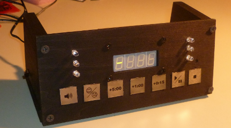
Gaming industry software engineer [Pedantite] writes in to let us know about his latest endeavor, an AVR based parental assistant timer: Good Times.   Looking for a new project that would be both useful and interesting, his wife suggested a “time out/ time’s up timer”. Like most of us [Pedantite]’s children are well studied in the arts of procrastination and mischief.  In the kids’ case this leads to time outs and break time running amok. The solution, in this case, is pretty much an advanced DIY egg timer with fun sounds.

The timer sports all of your basic countdown-timer functions including a 4 digit 7-segment LED output display, stop light style LED indicators, and controls to start/pause and stop the count down. The count down time can be input via the +5 minute, +1 minute, and +15 second buttons. There is even a happy/sad button to toggle between “time out” and “break time” modes. Two Atmel micros power the device, an AT Tiny 2313V for the capacitive touch keypad and an AT Mega 644P for the display, audio, and time measurement.  There are a lot of excellent techniques used in the build, some which we have covered here:  Four 595 Shift registers for the display; A 4 bit r2r DAC for audio output.

[Pedantite] is still in the process of writing up the project in multiple posts, and would love to know what you all want to hear about. Check out his blog for details and a quick video of the timer in action! Also, if you are interested in capacitive buttons, check out part 2 of the writeup.

Bluetooth Headset Battery Swap Keeps Going And Going…

bluetooth_headset_battery

[Reginaldo] purchased a cheap Bluetooth headset adapter, and while it worked well with all of his devices, he was disappointed to find that the battery life didn’t quite live up to the manufacturer’s claims. Advertised as capable of operating for 10 hours, he discovered that the device would typically die after only 7. He wanted more from the headset, so he took things into his own hands and replaced it with a much larger battery (Google Translation).

His goal was to keep the modifications as cheap as possible, so he repurposed a lot of items he had sitting around the house. He used a battery out of an old cell phone, with a capacity over six times greater than that of his original headset battery. He built a charging circuit using a MCP73863 microchip, specifically designed for managing Li-Ion/Li-Poly batteries. The Bluetooth headset was dismantled and repackaged in the shell of a cheap “audio amplifier” that he had on hand, along with the new battery and charging circuit. A nifty Hackaday logo was included on the outside of the new battery case, and the project was deemed complete.

[Reginaldo] reports that he is quite happy with his battery retrofit. The new power brick only takes about half an hour longer to charge, but can now be used for approximately 44 hours before requiring a recharge – not too shabby!

Everything You Need To Know About Wall Warts

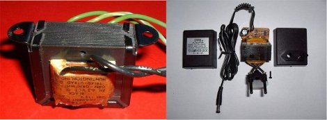
If you work with electronics at any skill level you need juice. [Jon] has a great, and clearly worded tutorial about Wall Wart Power Supplies with pretty much everything you need to know about those little black boxes hanging off of your outlets.

The whole thing starts off with the basics like transformers, rectification smoothing and regulation, then moves on to the different basic types, dedicating a page to linear, regulated and switching types, giving output performance charts under different situations.

Also included is a run-down of DC barrel jack structure so you get the right plug every time, wall wart type identification, a random sample comparison test, and a good selection of formulas to even keep the old hats reading along. Although you might want to set aside a little time at 9 pages and some Q/A in the comments, it might take a moment to read.