Unreadable Binary Epoch Clock Is Unreadable

binary-epoch-clock

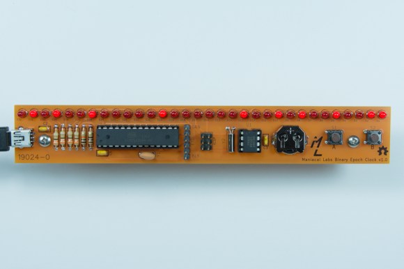
What time is it? For that matter, what is the date? This clock can tell you both of those things, if only you could read it. The inspiration for this Binary Epoch kit came after a friend of [Maniaclal Labs] built an eight-bit binary clock. That’s a pretty common project that gets riffed on for things like mains-timed logic-driven clocks. They figured why not make it bigger? But even then you can make some sense out of the display after studying it for just a bit, you won’t be much closer to answering those two questions.

The problem is that this is unreadable in a couple of different ways. First off, how long did it take you to figure out in your head the decimal equivalent of the binary number displayed above? We gave up. But pounding the number into Google (search for: 0b01010010000010000001001010010011 in decimal) gives us 1376260755. meaningful? Again, not to a human. This is Unix time, which is the number of seconds elapsed since the Epoch: 8/11/13-22:39:15.

Check out the video below that shows how to set the clock, which uses a menu system for human-friendly input. But since it’s Arduino compatible you can also connect an FTDI cable and program it from a computer. Oh, and since this is Open Source Hardware (note the icon in the lower right) you can get all the info to build (or breadboard) your own from their Github repo.

Here’s another complicated clock that uses Nixie tubes to display time and date info which is actually of use.

Continue reading “Unreadable Binary Epoch Clock Is Unreadable”

Making The Electronics For A Doppler Motion Sensor

There are many different sensors that can be used to detect motion in a given environment. Passive InfraRed (PIR) sensors are the most used today, as they work by detecting moving heat signatures. However, they are less reliable in the hotter days and obviously only work for animals and humans.

Sensors like the one shown in the above picture started to appear on the internet, they use the doppler effect to detect motion. I (limpkin) designed the electronics you need to add in order to get them to work.

Here is a simple explanation of the doppler effect: if you send an RF signal at a given frequency to a moving target, the reflected signal’s frequency will be shifted. It is commonly heard when a vehicle sounding a siren or horn approaches, passes, and recedes from an observer. The received frequency is higher (compared to the emitted frequency) during the approach, it is identical at the instant of passing by, and it is lower during the recession. Continue reading “Making The Electronics For A Doppler Motion Sensor”

Playing With An Oscilloscope You’ll (probably) Never Own

We’ll have to admit that we were really jealous when [Shahriar] sent us a video he made, in which he casually explains how a $500,000 160GS/s 62GHz oscilloscope works and then starts playing with it.

Even though you need to be quite familiar with electronics to fully understand the oscilloscope’s inner workings, [Shahriar]’s step by step explanation is still approachable for those who only understand the basics.

In the first half of the video he uses the manufacturer’s documentation which contains the oscilloscope block diagrams, so you’ll also learn about:

  • timer interleaved Analog to Digital Converters (ADCs), which allows you to increase your input sampling rate by using several of them
  • phase-locked loops, which use a reference clock to generate a much faster clock signal
  • custom made dies and the materials used for high frequency electronic components

In the second half of the video [Shahriar] connects a pseudo random binary sequence generator and uses the oscilloscope to make several measurements that you’d typically want to know for high speed signals (jitters, eye quality factor…). He later performs a small experiment where he up-converts the frequency components of two random 3.12Gbit/s signals and tries to recall each original signal using the oscilloscope functions, making this part of the video a bit harder to keep up with.

Designing A Pressure Sensitive Floor

ccm_activefloor8

[Sean] and his team at Adobe were asked to build “something new” for the Children’s Creativity Museum in San Francisco, so in several months they managed to build a digital/physical environment for kids called “Sense It”.

Part of this project involved designing and building a pressure-sensitive electronic floor which could detect if children were sitting, walking or running. As a camera based detection system couldn’t give them the type of precision they wanted, [Sean] decided to use pressure-sensitive resistors placed under MDF panels.

There are a total of twenty-one 2’x4′ tiles, each one including 8 pressure-sensitive resistors and an ATtiny84 based platform. All the microcontrollers digitize their 8 sensor signals and send their conversion results to a beaglebone over a shared i2c bus in a RJ45 CAT5 cable. As it is [Sean]’s first project, we will cut him some slack but several design mistakes have been made in our opinion:

  • Using i2c instead of RS485 / CAN for long distance data transmission
  • Digitizing the sensor voltages so far from them, as noise is added before the ADC
  • Sending the +5V required by the ATtiny in the RJ45 cable instead of a higher voltage (which would involve putting an LDO on the platforms)
  • Separating the digital and analog ground planes as the platform current consumption is low and transmission speeds slow

But the children who can now play with the complete system certainly won’t care. And you… what do you think of [Sean]’s work? Don’t hesitate to let us know in the comment section below.

Retrotechtacular: Understanding A Voltage Doubler

This very stern looking gentleman is about to explain how voltage doubles work in a plodding, yet satisfyingly thorough manner.

We’re not certain when this US Air Training Command video was produced. Obviously it was used to train servicemen who were responsible for keeping electronics running during war time. We’re glad for that, as they really found just the right balance to present a concept that required some knowledge, but is approachable for even the most basic of new electronics hackers.

The demonstration board shown on the right is the voltage circuit highlighted in the lesson. Here the pointing stick is being used to trace out the circuit function during one phase of the input transformer. The capacitor/diode pairs rectify the voltage, with the capacitors discharging in parallel series to double the output voltage. But how does the variable load (RL) affect the output? This is demonstrated under several different conditions using an oscilloscope to illustrate the change.

The discussion of how the diodes work reminded us of a modern tutorial we just ran across this weekend. It’s a bit bizarre, but explains the PN junction in a different way than we’re accustomed to. In this case you will already need to be familiar with how semiconductors work to understand the presentation.

Both clips can be found below the jump.

Continue reading “Retrotechtacular: Understanding A Voltage Doubler”

USB Adapter For An Old VT100 Keyboard

VT100

Ah, the VT100, the first dumb terminal that was controlled with a microprocessor. This ancient beast from the late 70s is quite unlike the terminals you’d find from even five years after its vintage – the keyboard connects via a TRS quarter-inch jack – the electronic and code design of this terminal is a bit weird. [Seth] was up to the challenge of making this mechanical keyboard work as a standard USB device, so he created his own USB adapter.

On the little quarter-inch to USB adapter, [Seth] included an HD 6402 UART to talk to the keyboard, along with a Teensy dev board and a few bits of circuits stolen from DEC engineers. The protocol between the keyboard and terminal is a little weird – first the terminal sets a bit in a status word, then the keyboard scans all the key rows and columns in sequence before telling the terminal it’s done. Yes, this gives the VT100 full n-key rollover, but it’s just weird compared to even an IBM Model M keyboard that’s just a few years younger.

[Seth] finally completed his circuit and wired it up on a perfboard. Everything works just as it should, although a little key remapping was done to keep this keyboard adapter useful for Mac and Windows computers. It’s a wonderful bit of kit, and any insight we can get into the old DEC engineers is a wonderful read in any event.

Vidias below.

Continue reading “USB Adapter For An Old VT100 Keyboard”

Just Swipe Your Card And Enter The Pin… What Could Go Wrong?

We do hope this project makes you shiver.

“Financial risks” is an audiovisual installation that reacts when you swipe your credit card and prints an odd looking receipt if you type in your pin-code. Even though the website contains few technical details (read none) about the build, we chose to feature the project as we find his intent interesting:

‘Financial Risks’ installation is a project designed to present an ironical viewpoint on encoded wallets, as a data input interface invites to overcome fear of impossibility to control spread of confidential information for the sake of curiosity of interaction with an object of art.

The piece consists of 6 bank card readers, a hardware system of sound and video synthesis, a keyboard for pin code entering, a 2-channel sound system and a cash register printer configured to print images. Up to 6 cards simultaneously may be used for playing.

We do hope that nothing is stored in the platform’s memory… but is the installation monitored?