A Beverage Cooler With A Stereo

Cooler

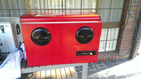
If you are looking for a way to spice up your summertime parties, try following [Pastryboy’s] lead. After letting the idea rattle around in his head for a few years, he finally built himself the cooler he always dreamed of.

[Pastryboy] was originally inspired by a YouTube video he found a few years ago. He took the basic concept and rolled with it. He started out with a mini fridge he found for $10. He removed the compressor and other plumbing bits. He also removed all of the internal shelving. Any leftover holes were patched up with silicone. Now when the fridge is laid on its back, it’s essentially the same as an ordinary cooler.

Next [Pastryboy] purchased two 6.5″ Boss speakers and an inexpensive head unit. He drilled a few pilot holes in the side of the refrigerator and then used a jigsaw to cut the holes to the proper sizes. Once the speakers were mounted in place, he needed to find a way to waterproof the inside. This was accomplished by using some small plastic bowls. The edges of the bowls were attached to the cooler wall using silicone.

[Pastryboy] was able to run most of the cabling through the inside of the cooler’s walls. The system is powered by a 12V lead acid battery. He chose a specific model of battery that can be stored in any orientation and that can handle being knocked around a little bit.

Next he added a couple of handles to the sides to make it easier to transport. A small bit of ski rope was attached to the inside of the lid, preventing the lid from flopping completely open. [Pastryboy] also added a drain to the bottom to make it easier for one person to empty the cooler. The final touch was to pretty it up a bit. He sanded down the entire thing and gave it several coats of red paint. The end result looks very slick.

[via Reddit]

Homemade Soldering Station for cheap Soldering Irons

Homemade Soldering Stations For Cheapy Irons

Everyone reading this post has had a cheap pencil-style soldering irons that plug straight into the wall at some point in their lives. Even if you’ve upgraded to a professional soldering station, you probably have one of these cheapy irons kicking around that are slow to heat up to an unknown temperature. [Pantelis] thought he could fix the latter problem with his Homemade Soldering Station for those basic soldering irons.

Since the intent of the soldering station was to control the temperature of the iron [Pantelis] had to figure out a way to sense the temperature. He did this by strapping a thermocouple to the iron near the tip. The wires were run back through the handle and then along the power cord.

Homemade Soldering Station for cheap Soldering Irons

Both the stock iron plug and the thermocouple leads plug into a box put together specifically for this project. In the photo you’ll notice the LCD screen that displays both the target and actual temperatures. The linear potentiometer below the LCD screen is used to set the target temperature. The LED to the right alerts the operator that the iron is heating up and when it is at temperature and read to go.

Although there isn’t a lot of schematic or part list information, [Pantelis] did do a good job photo documenting his build. Check it out, it’s worth a gander.

The Science Of Strengthening Glass

Strengthen Glass

[Ben Krasnow] is at it again. This time he’s explaining a simple method for strengthening glass. As usual, he does a fantastic job of first demonstrating and explaining the problem and then following it up with a solution.

[Ben] first uses a simple rig to place a controlled amount of force against a glass microscope slide. His experiment shows that the slide shatters once about 30psi of force has been applied to the center of the slide.

[Ben] then goes on to explain that current methods for producing glass leave many tiny impurities, or cracks, in the glass. As the glass slide flexes, the inside edge is placed into a compression force while the outside edge is under tension. The glass is more easily able to handle the compression force. The tension is where things start to break down. The tension force eventually causes those tiny impurities to spread, resulting in the shattering glass.

One possible solution to this problem is to find a way to fill in those tiny impurities. According to [Ben], most glass has sodium added to it in order to lower the melting temperature. [Ben] explains that if you could replace some of these smaller sodium atoms with larger atoms, you could essentially “fill” many of the tiny impurities in the glass.

[Ben] does this himself by heating up a small vat of potassium nitrate. Once the powder becomes molten, he submerges the glass slides in the solution for several hours. During this time, some of the sodium atoms are replaced by potassium atoms due to the natural process of diffusion.

Once the slides have cooled down, [Ben] demonstrates that they become much stronger. When placed in the testing rig, the stronger slides do not break until the pressure gets between 60psi and 70psi. That’s twice as strong as the original glass. All that extra strength from such a simple process. Be sure to watch the full video below. Continue reading “The Science Of Strengthening Glass”

Build An Efficient Inverter, Win A Million Dollars

Little Box Challenge

Google and the IEEE are giving away a million dollar prize to an individual or team, that can build the most efficient and compact DC to AC inverter. The goal is to design and build a 2kW inverter with a power density greater than 50W per cubic inch. To put that in perspective, conventional solar string inverters have power densities around 0.5-3W per cubic Inch, and microinverters around 5W per cubic Inch. So in other words, an order of magnitude more efficient than what we have now.

For the challenge, the inverter needs to convert 450VDC, with a 10 ohm series resistor simulating a solar array, to 240VAC @ 60Hz. Testing will consist of powering various resistive, inductive and capacitive loads ranging from 0-2kVA. The inverter is expected to regulate voltage within 5%, and frequency within 0.05%, while keeping the enclosure below 60 degrees C, and conforming to FCC Part 15 B (Unintentional radiators).

If you and/or your team can figure out the most efficient topology, switching frequency, novel use of high power wide bandgap (WBG) semiconductors, physically reduce the size of the input and output filters, and keep the whole thing running cool. Then get registered before the September 30, 2014 deadline. Inverters need to be functional and the results of this test procedure (PDF warning) sent in before July 22, 2015, then 18 finalists will be chosen to bring their inverters in person to a testing facility in the United States by October 21, 2015. The grand prize winner will be announced sometime in January, 2016

[Thanks for the tip Dmytro]

This Arduino power inverter would need a serious upgrade to enter. And speaking of entering challenges, it’s still not too late to enter our very own Hackaday Prize!

ATtiny Watering Timer Turns Off The Water When You Forget

ATtiny Water Timer

A pal of [Kyle’s] was regularly leaving his sprinkler on for too long. He also had forgotten to turn the water off while topping off his pool a couple of times, an embarrassing and wasteful situation. Being such a good friend, [Kyle] offered to make him a water timer. This isn’t a regular water timer that turns the water on and off at the same time every day. This device allows the user to push a button to have the unit switch on a solenoid valve, permitting water flow. After a predetermined amount of time the unit removes power to the solenoid valve which stops the water flow, successfully preventing pool overflows and excessive watering.

[Kyle] started off his design using a 555 chip to do the counting. He quickly became worried that timer lengths over 10 minutes would cause inconsistent functionality due to the leakage current of the capacitor and the charge current of the resistor. There are ways around this, but rather than complicate the design he switched to an ATtiny microcontroller. The added benefit of the ATtiny is that he could connect up a potentiometer to adjust the on-time without replacing parts or making a new unit. When the potentiometer is turned, the on-board LED will flash a number of times which corresponds with the delay in minutes. Ten flashes means a 10 minute delay. It’s a simple and clear interface.

As if the home etched PCB wasn’t cool enough, [Kyle] 3D printed up a case for the unit. The case permits access to the screw terminals and has provisions for the indicator LEDs. Check out the integrated flap in the top of the case. When this portion of the case is pushed in, it presses the PCB-mounted on/off switch.

If you are interested in making one, all of the files and code are available on [Kyle’s] site.

via [dangerous prototypes]

NFC Ring Lock Box

NFC Ring Lock Box

[Nairod785] wanted to build a lock box that would lock from the inside. He started with an inexpensive, plain wooden box. This kept the cost down but would also allow him to easily decorate the box later on using a wood burning tool.

To keep the box locked, he installed a simple latch on the inside. The latch is connected to a servo with string. When the servo rotates in one direction, it pulls the string and releases the latch. When the servo is rotated in the opposite direction, the latch closes and locks the box once again.

If you are going to have a locked box, then you are also going to need a key to open it. [Nairod785] used a ring with a built-in NFC tag, similar to the ring featured back in March. Inside of the box is a PN532 NFC module. The walls of the box were a little too thick for the reader to detect the ring, so [Nairod785] had to scratch the wall thickness down a bit. The NFC module is connected to an Arduino Nano. Communications are handled with I2C.

The NFC ring actually has two different NFC tags in it; one on each side. [Nairod785] had to program both of the tag ID’s into the Arduino to ensure that the ring would work no matter the orientation.

The system is powered by a small rechargeable 5V battery. [Nairod785] wired up a USB plug flush with the box wall so he can easily charge up the battery while the box is locked. It also allows him to reprogram the Arduino if he feels so inclined. There is also a power switch on the side to conserve energy.

The Berlin Cyberbeetle With Its Own TV

13_Cyberbeetle

The evolution of the mere beetle has transformed from organic matter into robotic gears, circuits, and wires. This Cyberbeetle project was born during an open culture hackathon in Berlin throughout a few months time period. The event was called Coding for Vinci and was held from April into July 2014. The project used an Arduino and combined openly licensed biology related pictures and sounds from the museums in the area in a fun and playful way.

[Kati] and [Tomi] based the design on a gorgeous Chalcosoma atlas beetle species which was found in insect box scans that were taken from a nearby museum. The cool thing about this project is that the Cyberbeetle that [Kati] and [Tomi] created has its own hi-tech insect box with various special features. For instance, when the box was rotated on its side, small doors were revealed that when opened unveiled a tiny home theater system with a hi-definition flat screen, audio system and infrared communication. Inside the horn of the Cyberbeetle was an infrared receiver, which allowed the creature to interface with its TV program when it started. Music videos as well excited the robotic insect.

The project was awarded the “Funniest hack” prize during the hackathon. And a video of it can be seen after the break:

Continue reading “The Berlin Cyberbeetle With Its Own TV”