An Introduction To Solid State Relays

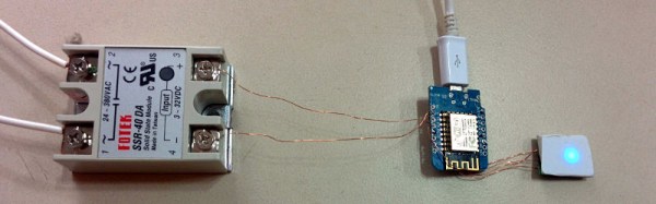
When we think of relays, we tend to think of those big mechanical things that make a satisfying ‘click’ when activated. As nice as they are for relay-based computers, there are times when you don’t want to deal with noise or the unreliability of moving parts. This is where solid-state relays (SSRs) are worth considering. They switch faster, silently, without bouncing or arcing, last longer, and don’t contain a big inductor.

Source Fotek SSR Specifications Sheet

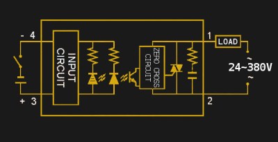
An SSR consists of two or three standard components packed into a module (you can even build one yourself). The first component is an optocoupler which isolates your control circuit from the mains power that you are controlling. Second, a triac, silicon controlled rectifier, or MOSFET that switches the mains power using the output from the optocoupler. Finally, there is usually (but not always) a ‘zero-crossing detection circuit’. This causes the relay to wait until the current it is controlling reaches zero before shutting off. Most SSRs will similarly wait until the mains voltage crosses zero volts before switching on.

If a mechanical relay turns on or off near the peak voltage when supplying AC, there is a sudden drop or rise in current. If you have an inductive load such as an electric motor, this can cause a large transient voltage spike when you turn off the relay, as the magnetic field surrounding the inductive load collapses. Switching a relay during a peak in the mains voltage also causes an electric arc between the relay terminals, wearing them down and contributing to the mechanical failure of the relay.

Continue reading “An Introduction To Solid State Relays”

Chess Robot’s Got The Moves

[RoboAvatar]’s Chess Robot consists of a gantry-mounted arm that picks up chess pieces and places them in their new location, as directed by the software. The game begins when the human, playing white, makes a move. When a play has been made, the human player presses a button to let the robot to take its turn. You can see it in action in the videos we’ve posted below the break.

Running the robot is an Arduino UNO with a MUX shield as well as a pair of MCP23017 I/O expander chips — a total of 93 pins available! Thanks to all those pins, the Arduino is able to listen to 64 reed switches, one for every square.

The robot detects the human’s move by listening to its reed switches and identifying when there is a change. The gantry consists of X and Y tracks made out of PVC slabs, with half-inch lead screws turned by NEMA-23s and powered by ST-6600 stepper drivers.

Unlike some chess robots that rely on pre-existing software, this one features a custom minimax chess algorithm that [RoboAvatar] coded himself. It consists of Python scripts run on a computer, which interacts with the Arduino via a serial connection. In the second video, he explains how his algorithm works. You can also download the Arduino and Python files from [RoboAvatar]’s GitHub repository.

You’d be surprised how many chess-playing robots we’ve published, like the ChessM8 robot and this voice-controlled chess robot.

Continue reading “Chess Robot’s Got The Moves”

Emulate ICs In Python

Most people who want to simulate logic ICs will use Verilog, VHDL, or System Verilog. Not [hsoft]. He wanted to use Python, and wrote a simple Python framework for doing just that. You can find the code on GitHub, and there is an ASCII video that won’t embed here at Hackaday, but which you can view at ASCIInema.

Below the break we have an example of “constructing” a circuit in Python using ICemu:

Continue reading “Emulate ICs In Python”