Charge All Your Batteries With USB PD

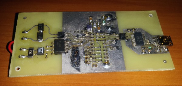
USB-C has been around for a while, and now that it can charge phones and Macbooks and Thinkpads, the hackers are starting to take note of power adapters that can supply lots of current. [Alex] was turned on to USB-C after he charged a laptop, Nintendo Switch, and phone with one power adapter. This led him to create a USB-C battery charger for all your LiPos.

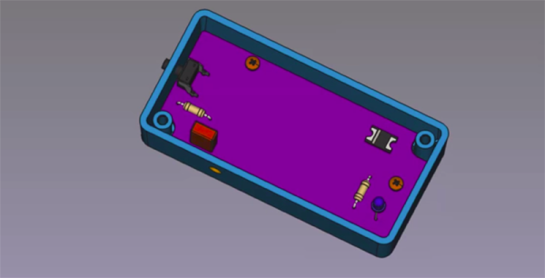
The high-level design of this project is simply a board with a USB C port on one end, an XT60 plug on the other, and some support for balance leads. Plug this board into a USB C adapter, plug a battery in, and the battery will charge automagically. The only UI is an RGB LED. It’s difficult to imagine a battery charger that’s easier to use.

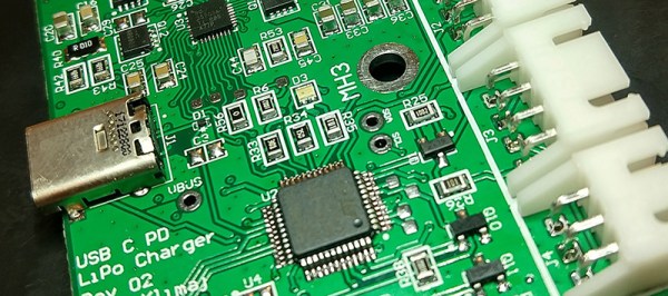
For the electronics, [Alex] is using an STM32G0 for the smarts of the device, which includes handling the USB PD spec. This gives the charger 20 Volts to play with, and this is then regulated and sent into the battery. Right now, this board will charge 2-4c batteries. That’s a good enough proof of concept to charge some quadcopter batteries, or just as a really simple way to charge some LiPo cells.

Sound Card ADCs For Electrocardiograms

Every few years, or so we’re told, [Scott] revisits the idea of building an electrocardiogram machine. This is just a small box with three electrodes. Attach them to your chest, and you get a neat readout of your heartbeat. This is a project that has been done to death, but [Scott]’s most recent implementation is fantastic. It’s cheap, relying on the almost absurd capability for analog to digital conversion found in every sound card, and the software is great. It’s the fit and finish that makes this project shine.

The hardware for this build is simply an AD8232, a chip designed to be the front end of any electrocardiogram. This is then simply connected to the microphone port of a sound card through a 1/8″ cable. For the exceptionally clever, there’s a version based on an op-amp. It’s an extraordinarily simple build, but as with all simple builds the real trick is in the software. That’s where this project really shines, with custom software with graphics, and enough information being displayed to actually tell you something.

We’ve seen a number of sound card ADCs being used for electrocardiograms in the past, including some from the Before Times; it makes sense, sound cards are the cheapest way to get a lot of analog data very quickly. You can check out [Scott]’s demo video out below.

Continue reading “Sound Card ADCs For Electrocardiograms”

This GPS Speedometer Hangs Off Your Handlebars

If you can ride a bike with no handlebars, no handlebars, no handlebars, you can do just about anything. You can take apart a remote control, and you can almost put it back together. You can listen in on a two meter repeater and you can build a GPS module speedometer. That’s what [Jeremy Cook] did with just a few parts, a little 3D design, and some handy zip ties to hold it onto the handlebars, the handlebars.

The electronics for this build are relatively simple, based on an Arduino Pro Mini because that’s just about the smallest readily available development board you’ll be able to find. To this is a LiPo, a LiPo charging circuit, a GPS module, and a single RGB LED. The code gets some data from the GPS module and figures out a speed. This is then translated into a color — red, yellow, or green depending on whether you’re stationary, below 5 km/h, or above 5 km/h.

All these electronics are stuffed into a 3D-printed enclosure. The majority of the enclosure is printed in black, with a translucent top that serves as a great diffuser for the LED. Just two zip ties hold this GPS speedometer onto the handlebars, and from the video below, everything looks great. The GPS module does take some time to get data at first, but that’s a common problem with GPS units that have been powered off for a few days. If only someone made a GPS module that could keep time with no metronome, with no metronome.

Continue reading “This GPS Speedometer Hangs Off Your Handlebars”

Texting With A Teletype

How do you get the kids interested in old technology? By connecting it to a phone, obviously. Those kids and their phones. When [Marek] got his hands on an old-school teletype, he hooked it up to a GSM network, with all the bells and whistles including a 40mA current loop running at an impressive 50 baud.

The teletype in question here is a vintage T100 teletype manufactured in Czechoslovakia sometime in the ’70s. This was a gift to [Marek]’s workplace, the museum of Urban Engineering in Cracow, and this project is effectively an experiment to investigate the possibility of running this teletype as an interactive exhibit rather than an artefact from the age of current loops and phone systems.

The current loop is, or was, the standard way of connecting a teletype to anything, so all [Marek] had to do was construct a box that translated the signals from a GSM modem to this current loop. For the prototype, the microcontroller in question is an old AT89C2051 (as that’s what was sitting in the parts drawer). This was moved over to a PIC32 microcontroller and a SIM800 GSM module. This is housed in a two-part enclosure, with the GSM interfaced housed in one half, with the current loop generator consisting of a simple DC power supply housed int the other half.

This interface is capable of receiving and sending messages from the keyboard to a GSM network, so it is theoretically possible you could text your friends using an old-school teletype. This functionality hasn’t been implemented yet, but it is just about the coolest thing you could possibly imagine. You can check out a video of the teletype in action below. Continue reading “Texting With A Teletype”

Need A Small Keyboard? Build Your Own!

If you want keyboards, we can get you keyboards. If you want a small keyboard, you might be out of luck. Unless you’re hacking Blackberry keyboards or futzing around with tiny tact switches, there’s no good solution to small, thin, customization keyboards. There’s one option though: silicone keyboards. No one’s done it yet, so I figured I might as well.

Unfortunately, there is no readily available information on the design, construction, or manufacture of custom silicone keypads. There is a little documentation out there, but every factory that does this seems to have copy and pasted the information from each other. Asking a company in China about how to do it is a game of Chinese Whispers. Despite this, I managed to build a custom silicone keypad, and now I’m sharing this information on how to do it with you.

Continue reading “Need A Small Keyboard? Build Your Own!”

A Year-Long Experiment In OLED Burn-In

If you need to add a small display to your project, you’re not going to do much better than a tiny OLED display. These tiny display are black and white, usually found in resolutions of 128×64 or some other divisible-by-two value, they’re driven over I2C, the libraries are readily available, and they’re cheap. You can’t do much better for displaying a few numbers and text than an I2C OLED. There’s a problem, though: OLEDs burn out, or burn in, depending on how you define it. What’s the lifetime of these OLEDs? That’s exactly what [Electronics In Focus] is testing (YouTube, in Russian, so click the closed captioning button).

The experimental setup for this is eleven OLED displays with 128×64 pixels with an SSD1306 controller, all driven by an STM32 over I2C. Everything’s on a breadboard, and the actual display is sixteen blocks, each lit one after another with a one-second display in between. This is to test gradually increasing levels of burnout, and from a surface-level analysis, this is a pretty good way to see if OLED pixels burn out.

After 378 days of testing, this test was stopped after there were no failed displays. This comes with a caveat: after a year of endurance testing, there were a few burnt out pixels. correlating with how often these pixels were on. The solution to this problem would be to occasionally ‘jiggle’ the displayed text around the screen, turn the display off when no one is looking at it, or alternatively write a screen saver for OLEDs. That last bit has already been done, and here are the flying toasters to prove it. This is an interesting experiment, and although that weird project you’re working on probably won’t ping an OLED for a year of continuous operation, it’s still something to think about. Video below.

Continue reading “A Year-Long Experiment In OLED Burn-In”

Mechanical Integration With KiCad

Eagle and Fusion are getting all the respect for integrating electronic and mechanical design, but what about KiCad? Are there any tools out there that allow you to easily build an enclosure for your next printed circuit board? [Maurice] has one solution, and it seamlessly synchronizes KiCad and FreeCAD. KiCad will give you the board, FreeCAD will give you the enclosure, and together you have full ECAD and MCAD synchronization.

This trick comes in the form of a FreeCAD macro (on the Github, with a bunch of documentation) that loads a KiCad board and components into FreeCAD and export them as a STEP file. You can align the KiCad board in FreeCAD, convert STEPs to VRMLs, check interference and collision, and create an enclosure around a KiCad board.

KiCad has gotten some really great visualization tools over the past few years, and we would be remiss if we didn’t mention it’s one of the best ways to visualize a completed circuit board before heading to production. Taking that leap from electronic CAD to mechanical CAD is still something that’s relatively rare in the KiCad ecosystem, and more tools to make this happen is always wanted.