From a practical standpoint, [John] may be correct that his recent creation is the “world’s worst digital dash”, but we’re still oddly enamored with the idea of using a Nintendo Game Boy as a digital speedometer. Pulling it off meant interfacing the handheld with the vehicle’s CAN bus system, so whether you’re into retro gaming or car hacking, this project has something to offer.
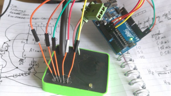
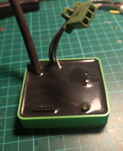
Showing real-time vehicle speed on the Game Boy sounds like it should be relatively easy, but the iconic game system wasn’t exactly built for such a task. Its 2 MHz CPU and 160×144 pixel dot-matrix screen were every kid’s dream in 1989, but using it as a car dashboard is pushing it. To bridge that gap, [John] designed two custom circuit boards. One interfaces with the Game Boy, intercepting its memory requests and feeding it data from a microcontroller. The other processes the CAN bus signals, translating speed information into a form the Game Boy can display. [John] used inexpensive tools and software to read the CAN bus data, and used GBDK-2020 to write the software in C. His video goes in great detail on how to do this.
Months of work have gone into decoding the Game Boy’s data bus and creating a schematic for the interface board. Tricking the Game Boy into thinking it was loading a game, while actually displaying incoming speed data. The screen’s low resolution and slow refresh rate rendered it barely readable in a moving vehicle. But [John]’s goal wasn’t practicality — it was just proving it could be done.
Want to dive deep into the Game Boy? Have you seen the Ultimate Game Boy talk?
Continue reading “A Game Boy Speedometer, Just Because You Can”